Insulator bracket

An insulator and frame technology, which is applied in the field of insulator storage equipment, can solve the problems of troublesome device access, inconvenience in counting the number of composite insulators, affecting the working performance of composite insulators, etc., and achieves the effect of convenient access and convenient access to composite insulators.

Active Publication Date: 2017-09-01
JINAN LICHENG POWER SUPPLY CO OF STATE GRID SHANDONG ELECTRIC POWER CO +1
View PDF5 Cites 3 Cited by
  • Summary
  • Abstract
  • Description
  • Claims
  • Application Information

AI Technical Summary

Problems solved by technology

At present, when storing and transporting composite insulators, the composite insulators after the inspection process are generally placed horizontally on one side of the shelf. After one side is full, the shelf is turned so that the other side faces the operating equipment, and the other One side is full of products, and finally pulled away. This method needs to provide more room for movement because the car needs to turn, especially for long products, which require more space and will encounter a lot of trouble during the transfer process.
Moreover, multiple composite insulators are stacked horizontally on the shelf. Since the length of composite insulators is generally between 1 and 2 meters, it takes up a lot of space for storage. In addition, the horizontal stacking method is very inconvenient for counting the number of composite insulators. Moreover, the product will be deformed due to the

Method used


Image

  • Insulator bracket
  • Insulator bracket
  • Insulator bracket

Examples


Embodiment Construction

[0029] In order to facilitate those of ordinary skill in the art to understand and implement the present invention, the present invention will be further described in detail below in conjunction with the accompanying drawings and embodiments, but the embodiments of the present invention are not limited thereto.

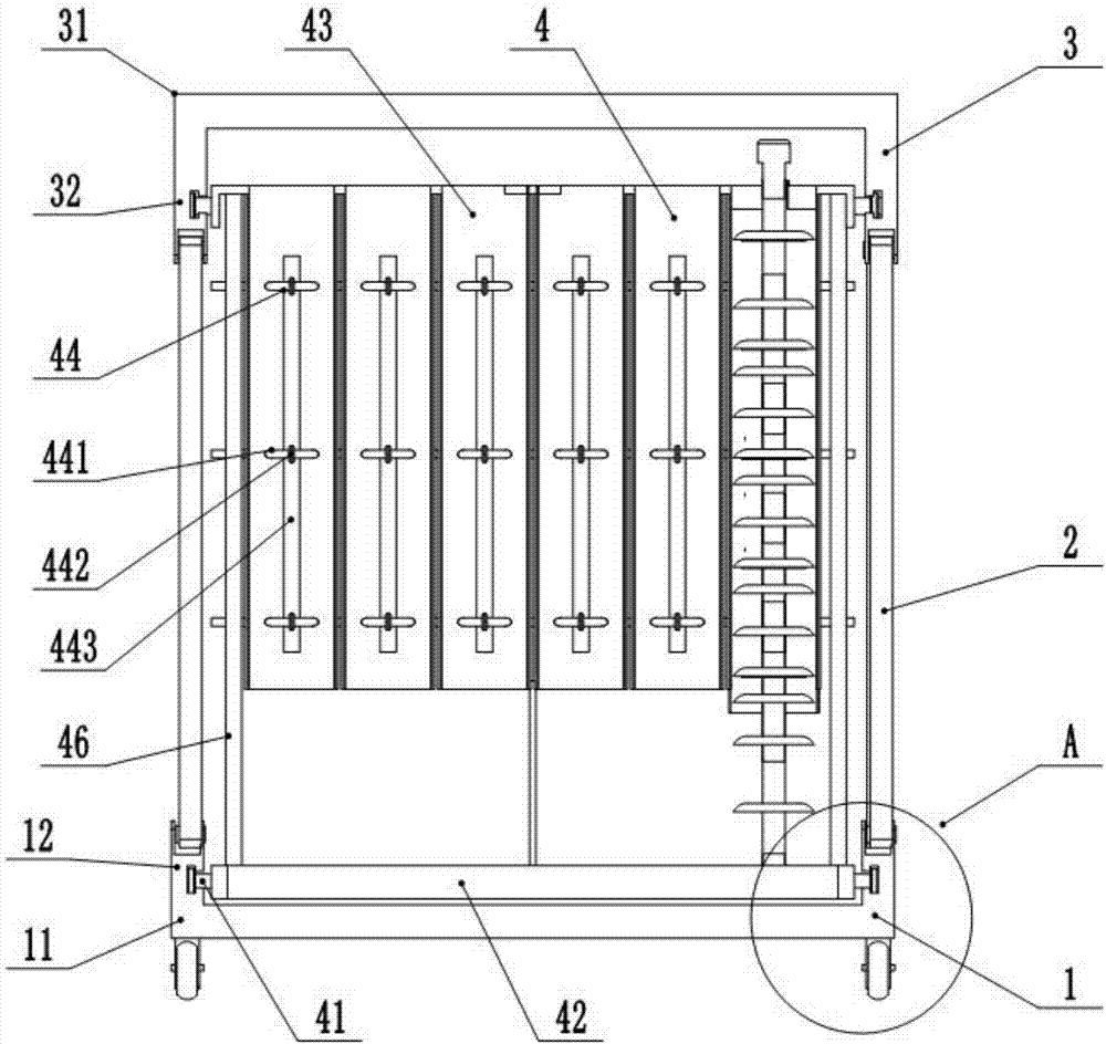
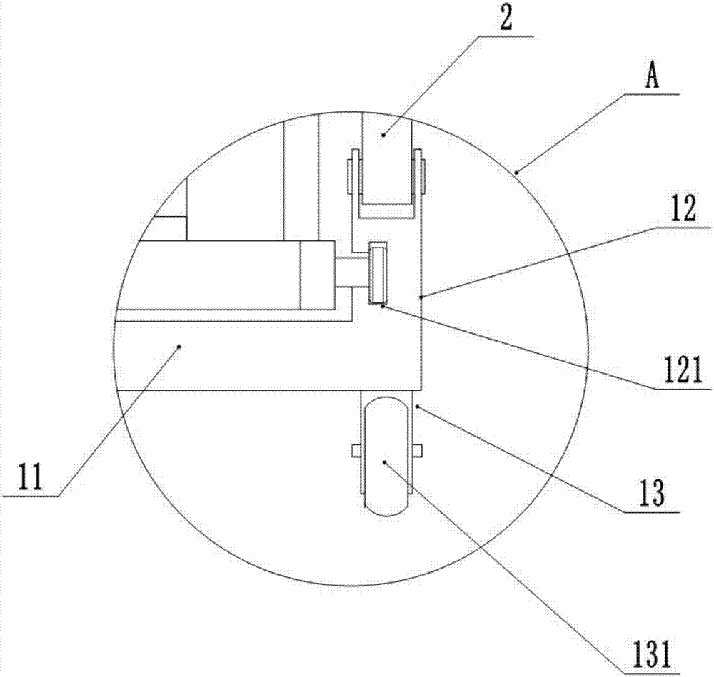
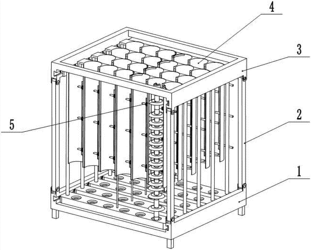
[0030] as attached figure 1 Shown in -6, an insulator support includes a lower support 1, an upper support 3, a column 2 and a storage device 4, the lower support 1 includes a lower frame 11 and a lower vertical plate 12, and the upper support 3 includes an upper frame 31 and The upper vertical board 32, the uprights 2 are arranged on the four corners of the lower vertical board 12 and the upper vertical board 32, the upper vertical board 32 and the lower vertical board 12 are provided with a through chute 121, and the storage device 4 includes a support Plate 42 and arc-shaped plate 43, described arc-shaped plate 43 is connected with support plate 42 by connecting ro...


PUM


Abstract

The invention discloses an insulator bracket. The insulator bracket comprises a lower bracket body, an upper bracket body, stand columns and storage devices. The lower bracket body comprises a lower frame and lower vertical plates, the upper bracket body comprises an upper frame and upper vertical plates, the stand columns are arranged at four corner ends of the lower vertical plates and four corner ends of the upper vertical plates, and the upper vertical plates and the lower vertical plates are provided with through sliding slots; the storage devices comprise supporting plates and arc plates, the arc plates and the supporting plates are connected through connection rods, the multiple arc plates are connected to form a placement plate, the two ends of the placement plate and the two ends of the supporting plates are provided with guide wheels, and the guide wheels are arranged in the sliding slots; the arc plates are provided with matched plates, the matched plates comprise semi-circular arc plates and suspension loops, the suspension loops are arranged on the upper portions of the semi-circular arc plates, rotary rods are arranged on the upper portions of the suspension loops, the tail ends of the rotary rods are provided with clamp hoops, the suspension loops are connected with the upper ends of the arc plates, and composite insulator strings of different types can be stored, the composite insulator strings can be stored and taken conveniently, and an auxiliary function of hoisting composite insulators is achieved.

Description

technical field [0001] The invention relates to the technical field of insulator storage equipment, in particular to an insulator support. Background technique [0002] Composite insulator is a kind of composite insulator products. Its structure is to set a fitting at one end of the mandrel of a general composite insulator. Composite insulators and post composite insulators have different bases, and the hardware above them is roughly the same. The cross-arm composite insulator is a flat block, the base of the pin composite insulator is a cylindrical block, and the base of the post composite insulator is a disc block. At present, the general Composite insulators are between 1 and 2 meters in length. [0003] With the continuous increase of power grid projects, the demand for composite insulators is also increasing. At present, when storing and transporting composite insulators, the composite insulators after the inspection process are generally placed horizontally on one si...

Claims


Application Information

Patent Timeline
IPC IPC(8): B65D61/00
CPCB65D61/00
Inventor 胥超万旭庄力行刘华博苗垒
Owner JINAN LICHENG POWER SUPPLY CO OF STATE GRID SHANDONG ELECTRIC POWER CO
Why Eureka
Try Eureka