Deep foundation pit concrete supporting structure with hoisting holes being pre-formed and construction method thereof

A technology for supporting structures and construction methods, which is applied in basic structure engineering, excavation, construction, etc., can solve the problems of mutual interference of working faces, overlapping construction procedures, and increased hoisting risks, so as to improve hoisting safety, hoisting stability and safety, The effect of reducing the risk of lifting

Pending Publication Date: 2017-09-01
SINOHYDRO BUREAU 8 CO LTD
View PDF5 Cites 1 Cited by
  • Summary
  • Abstract
  • Description
  • Claims
  • Application Information

AI Technical Summary

Problems solved by technology

[0004] Due to the short concrete blocks, if the steel wire ropes are not properly bound during the hoisting process, it is prone to tilting or even falling, which is extremely risky; moreover, the construction procedures of the subway station overlap, the working surfaces interfere with each other, and there are ma

Method used


Image

  • Deep foundation pit concrete supporting structure with hoisting holes being pre-formed and construction method thereof
  • Deep foundation pit concrete supporting structure with hoisting holes being pre-formed and construction method thereof
  • Deep foundation pit concrete supporting structure with hoisting holes being pre-formed and construction method thereof

Examples


Embodiment

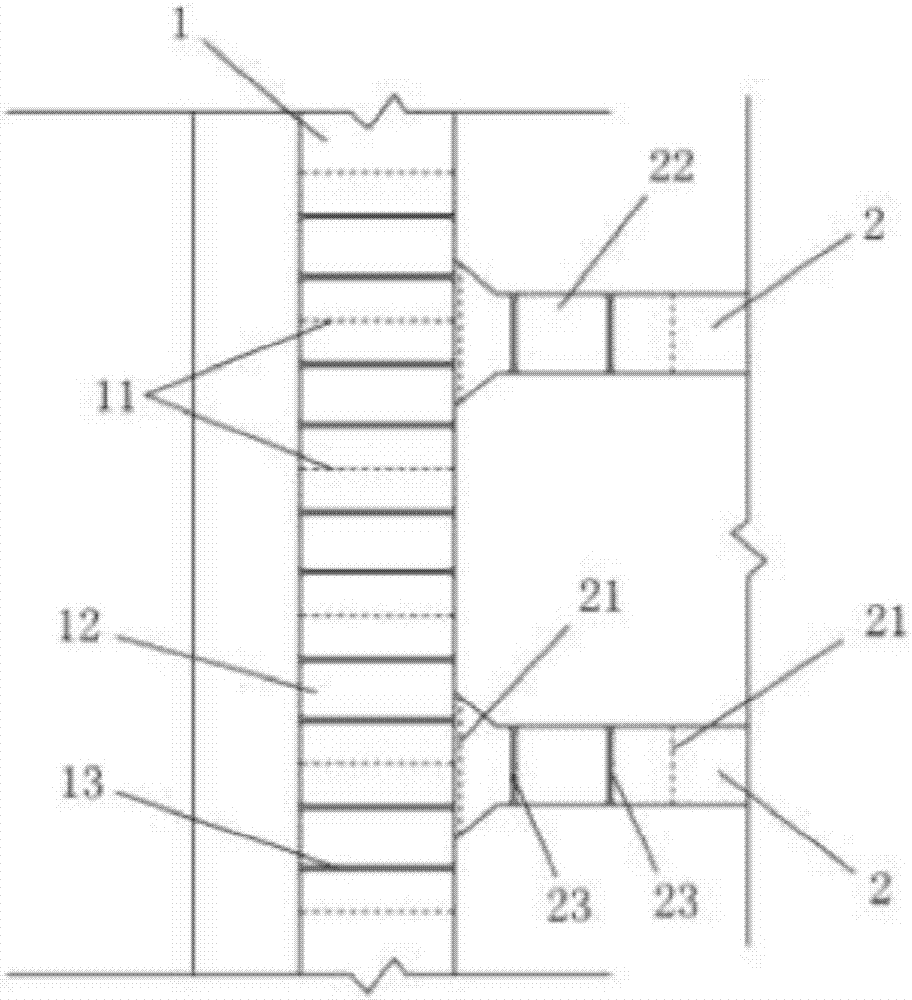
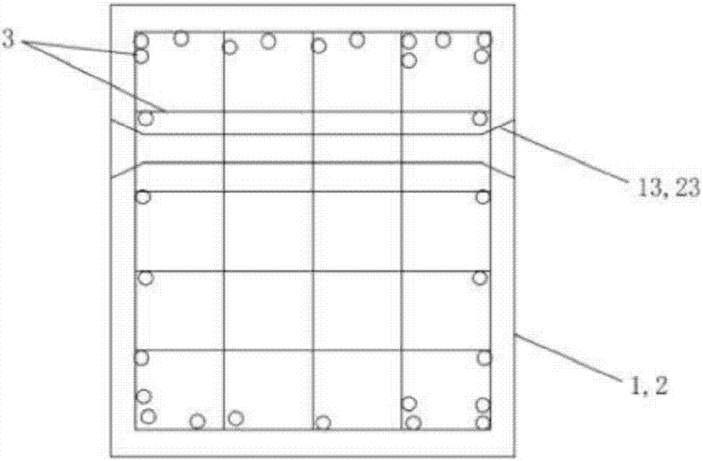
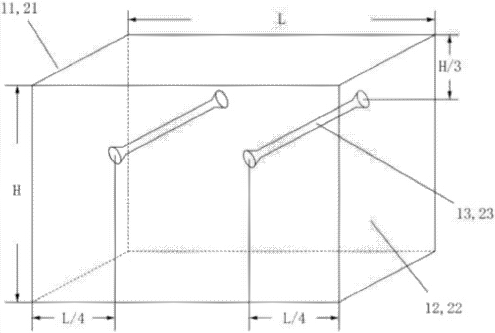
[0037] Such as Figure 1 to Figure 4 As shown, the present invention is an embodiment of the deep foundation pit concrete support structure with preset hoisting holes. The concrete support structure of the deep foundation pit includes concrete waist beams 1 and concrete supports 2 connected to each other. The concrete waist beam 1 has a plurality of waist beam pre-cut surfaces 11, and the plurality of waist beam pre-cut surfaces 11 divide the concrete waist beam 1 into two parts. There are a plurality of waist beam pre-cut sections 12, and each waist beam pre-cut section 12 is pre-embedded with a waist beam hoisting hole pipe 13 for passing a hoisting steel wire rope. Preferably, two waist beam hoisting hole pipes 13 are pre-embedded side by side along the length direction of the concrete waist beam 1 in each waist beam pre-cut section 12 . The waist beam hoisting hole pipe 13 is arranged on the top of the concrete waist beam 1 along the transverse direction of the concrete w...


PUM

PropertyMeasurementUnit
Lengthaaaaaaaaaa
Diameteraaaaaaaaaa

Abstract

The invention discloses a deep foundation pit concrete supporting structure with hoisting holes being pre-formed and a construction method thereof. The concrete supporting structure comprises a concrete waist beam and concrete supports which are mutually connected; the concrete waist beam is provided with a plurality of waist beam pre-cutting surfaces; the multiple waist beam pre-cutting surfaces divide the concrete waist beam into a plurality of waist beam pre-cutting sections; and a waist beam hoisting hole pipe is arranged in each waist beam pre-cutting section in a penetrating and pre-buried mode. The concrete supporting structure can guarantee hoisting safety of concrete supporting blocks. The construction method of the concrete supporting structure comprises the steps that structural steel bars of the concrete waist beam and the concrete supports are bound; the waist beam hoisting hole pipes and supporting hoisting hole pipes are arranged in the concrete waist beam and the concrete supports correspondingly, and the waist beam hoisting hole pipes and the supporting hoisting hole pipes are bound on the structural steel bars through binding wires; and a formwork is erected, the concrete waist beam and the concrete supports are poured, and the formwork is removed after pouring The construction method is simple and feasible, and the situation that in concrete pouring, the waist beam hoisting hole pipes and the supporting hoisting hole pipes are dislocated can be avoided.

Description

technical field [0001] The invention relates to the technical field of deep foundation pit construction, in particular to a concrete support structure for a deep foundation pit with preset hoisting holes and a construction method thereof. Background technique [0002] For urban subway station foundation pits with large construction area and large excavation depth, the supporting structure is usually partly or even fully supported by concrete to maintain the stability of the foundation pit. In recent years, wire saws have been used more and more widely in the demolition of concrete supports. Usually, wire saws are used to cut concrete supports into concrete blocks of 8t to 10t, and the concrete blocks are transported to designated locations by forklifts, and then hoisted by cranes. Out of the foundation pit and transported away. [0003] Typically, the length of the cut concrete support is around 2.5m, sometimes even shorter. Taking a subway station as an example, the desig...

Claims


Application Information

Patent Timeline
IPC IPC(8): E02D17/04
CPCE02D17/04
Inventor 肖育斐易军旗刘五一王巧华王石溪阳军生王立川施广鑫
Owner SINOHYDRO BUREAU 8 CO LTD
Why Eureka
Try Eureka