
Blade hoisting equipment

A technology for hoisting equipment and blades, which is used in transportation and packaging, load hoisting components, and assembly of wind turbines, etc., can solve the problems of no oblique-inserted single-blade hoisting, long time for turning the impeller, and reduced installation efficiency of the unit. , to achieve the effect of reducing tooling development costs, increasing process diversity, and increasing hoisting safety

Active Publication Date: 2021-06-25
JIANGSU GOLDWIND SCI & TECH CO LTD
View PDF5 Cites 0 Cited by
  • Summary
  • Abstract
  • Description
  • Claims
  • Application Information

AI Technical Summary

Problems solved by technology

For the installation of blades in a vertical posture, there is currently only horizontal single-blade hoisting, but no oblique single-blade hoisting
[0003] For horizontal single-blade hoisting, corresponding turning tooling is required, that is, when the blade is installed horizontally in the air, it is necessary to turn the pitch bearing in the hub to the horizontal state through turning tooling in advance, and the time for turning the impeller is relatively short. Long, it usually takes more than two hours to bring a pitch bearing disc to the horizontal attitude, which reduces the installation efficiency of the unit and takes a long time to install

Method used


Image

  • Blade hoisting equipment
  • Blade hoisting equipment

Examples


Embodiment Construction

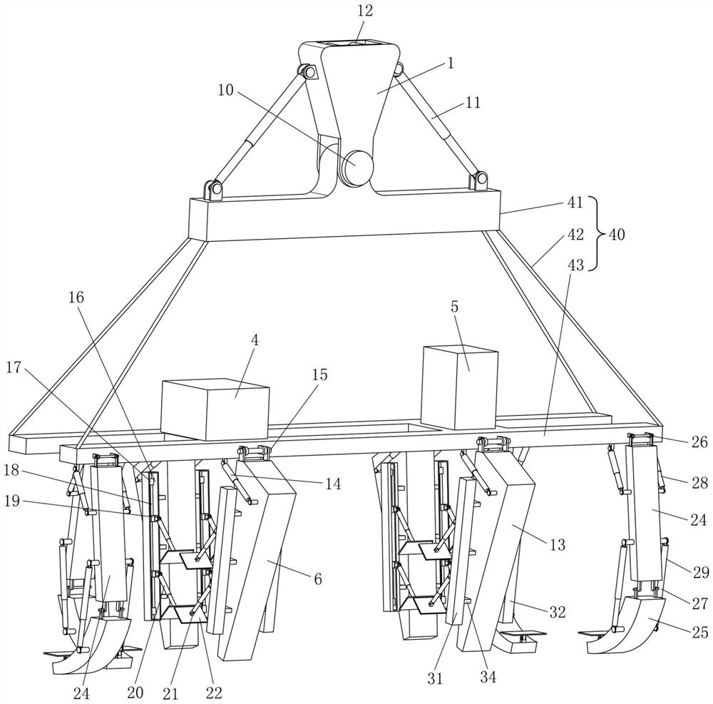
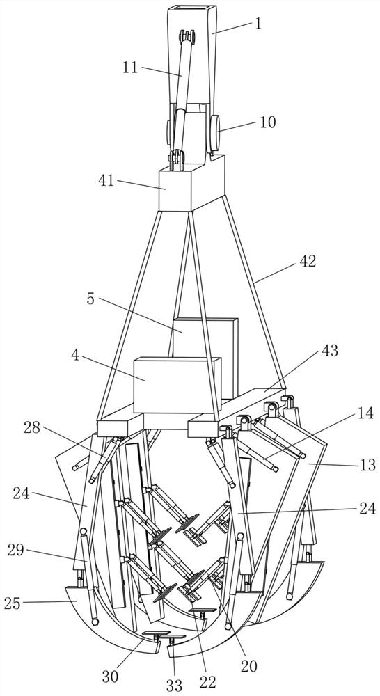
[0028] Embodiments of the present invention will be specifically described below in conjunction with the accompanying drawings.

[0029] refer to figure 1 and figure 2 , the blade hoisting device according to the present invention may include: a suspension beam 1; a spreader frame 40; coupled to the suspension beam 1; a clamping mechanism, mounted on the spreader frame 40, and including A blade web clamp for clamping the position of the blade web and a blade leading edge support clamp for holding the position of the blade leading edge are arranged to clamp the blade in a state where the blade leading edge faces downward.

[0030] The blade web clamp may comprise at least one web clamping unit, and each web clamping unit comprises two web clamping arms disposed facing each other in the width direction of the spreader frame 40, with A clamping space is formed between the web clamping arms, and one end of each web clamping arm is pivotally coupled to the spreader frame 40, so ...


PUM


Abstract

The invention provides blade hoisting equipment. The blade hoisting equipment is characterized in that the blade hoisting equipment comprises a hoisting beam, a lifting appliance frame and a clamping mechanism; the lifting appliance frame is combined to the hoisting beam; the clamping mechanism is installed on the lower portion of the lifting appliance frame and comprises a blade web plate clamp and a blade front edge supporting clamp which are arranged in the length direction of the lifting appliance frame at intervals, the blade web plate clamp is used for clamping the blade web plate position, and the blade front edge supporting clamp is used for supporting the blade front edge position; and the blade front edge supporting clamp comprises multiple front edge supporting units, the multiple front edge supporting units are arranged on the two sides of the lifting appliance frame in the width direction and arranged in a staggered manner in the length direction of the lifting appliance frame, each of the multiple front edge supporting units is pivotally connected to the lifting appliance frame, and each front edge supporting unit comprises a bottom supporting plate which faces upwards. According to the blade hoisting equipment, blades in the vertical posture can be clamped, universality is achieved for different blades, meanwhile, large clamping space is achieved, and the adjustable oblique insertion angle range is wide.

Description

technical field [0001] The invention relates to the technical field of wind power generation, in particular to a hoisting device for installing blades in a vertical posture. Background technique [0002] The blade hoisting of domestic large-scale offshore wind turbines has gradually begun to use the single-blade hoisting method, that is, the corresponding single-blade spreader has been developed to clamp and install the blade with a single support. At present, the main ways of single-blade hoisting include: the installation of the blade in a horizontal posture and the installation of the blade in a vertical posture. The installation of the blade in the horizontal attitude includes two types: horizontal single-blade hoisting, that is, the blade is docked with the pitch bearing in the air in the horizontal direction; oblique single-blade hoisting, that is, the blade is docked with the pitch bearing in the air. Carried out at an angle to the horizontal. As for the installatio...

Claims


Application Information

Patent Timeline
IPC IPC(8): B66C1/44B66C13/08F03D13/10
CPCB66C1/108B66C1/447B66C13/08F03D13/10Y02E10/72
Inventor 沈星星张竹程伟
Owner JIANGSU GOLDWIND SCI & TECH CO LTD
Learn More