
Forward motion compensation method for three-axis gyroscope-stabilized platform

A gyro-stabilized platform and image motion compensation technology, which is applied to measuring devices, instruments, etc., can solve problems such as blurred images, and achieve the effect of increasing operating efficiency and improving surveying and mapping accuracy

Active Publication Date: 2017-09-01
长春长光睿视光电技术有限责任公司
View PDF4 Cites 2 Cited by
  • Summary
  • Abstract
  • Description
  • Claims
  • Application Information

AI Technical Summary

Benefits of technology

This patented technology allows for better quality images captured by an airborne camera without shifting more than two or three times per second during flight. It achieves this through adjustment on how long it takes each picture before capturing another one. By adding backward movement compensating functions at different stages within the process, stabilized platforms can capture higher speeds and altitudes while maintaining good depth resolution compared to traditional methods like film cameras.

Problems solved by technology

This patents describes different ways to fix an aeronium photo machine onto its surface while maintaining stability. Current methods have limitations in achieving these goals: (1) they require accurate orientation between the machine and the target; (2) their ability to correct any rotation or other disturbances affecting the alignment direction makes them difficult to achieve overall, leading to poor overall performance and reduced usability of the cameras themselves.

Method used


Image

  • Forward motion compensation method for three-axis gyroscope-stabilized platform
  • Forward motion compensation method for three-axis gyroscope-stabilized platform
  • Forward motion compensation method for three-axis gyroscope-stabilized platform

Examples


Embodiment Construction

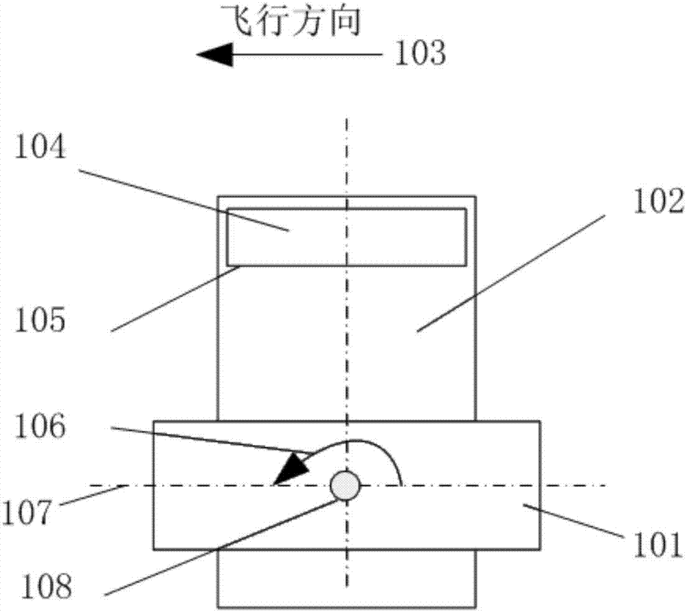
[0036] Such as figure 1 As shown, an aerial photographic device 102 is installed on a three-axis gyro-stabilized platform 101 , and the image plane 105 of a detector 104 on the aerial photographic device faces downward. The aircraft flies along the direction 103 , and the pitch axis 108 of the stabilized platform rotates along the direction 106 when the forward image motion is compensated. When the aerial photography equipment takes pictures, the ideal state of the stable platform is to make the working plane 107 horizontal, the pitch angle is 0, and the pitch angular velocity is kept so that the image movement speed on the image plane 105 is 0.

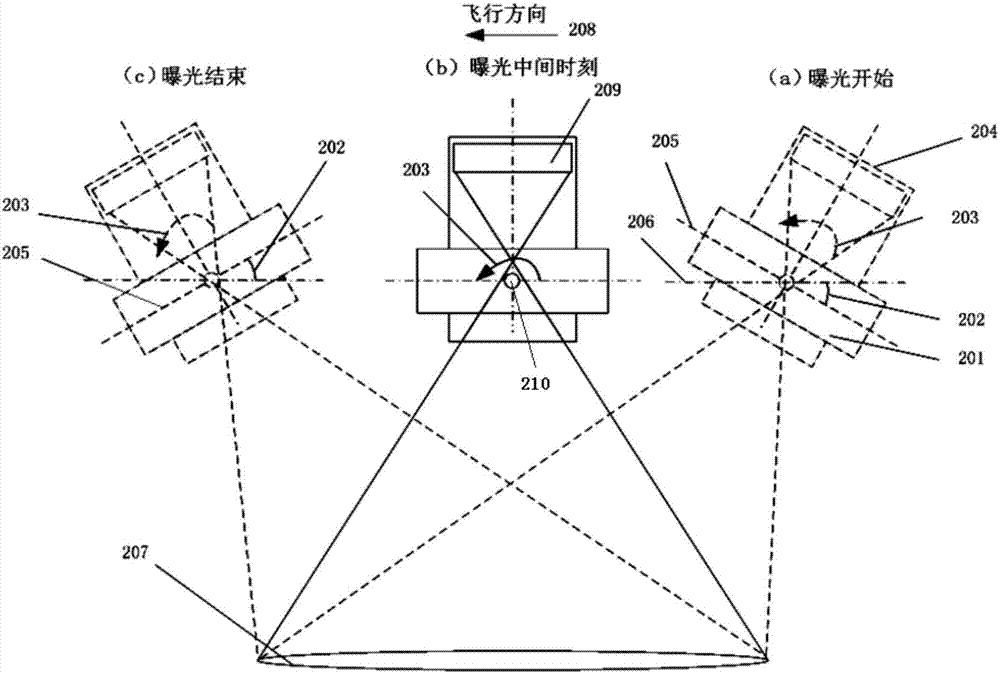
[0037] The forward image motion compensation method of the three-axis gyro-stabilized platform of the present invention, during the exposure process, the stable platform and the movement of the aerial photography equipment are as follows: figure 2 As shown, (a), (b) and (c) in the figure respectively represent the schematic diagram...


PUM


Abstract

The invention relates to a forward motion compensation method for a three-axis gyroscope-stabilized platform. The method comprises the following steps: acquiring a velocity and a flight height of a plane in real time, and calculating a velocity-height ratio; when the velocity-height ratio exceeds a set value, controlling a stabilized platform to perform reciprocation movement once in a pitch direction within a shooting cycle of each frame of images of aerial photographic equipment, wherein the reciprocation movement of the stabilized platform consists of an initial position holding section, an accelerated rotation section, a uniform velocity rotation section and an initial position return section. By adopting the method, a forward motion compensation function is added for the stabilized platform, so that the stabilized platform with the aerial photographic equipment is applicable to situations with relatively large velocity-height ratios, the working efficiency is improved, and the surveying and mapping precision is improved.

Description


Claims


Application Information

Patent Timeline
Owner 长春长光睿视光电技术有限责任公司
Features
  • Generate Ideas
  • Intellectual Property
  • Life Sciences
  • Materials
  • Tech Scout
  • Unparalleled Data Quality
  • Higher Quality Content
  • 60% Fewer Hallucinations
Learn More