A machine oil alarm joint leakage-proof structure

An alarm, anti-leakage technology, applied in the direction of fixed/insulated contact members, connections, connection parts installation, etc., can solve problems such as poor sealing performance, product quality decline, short service life of oil alarms, etc., to enhance quality performance , The effect of improving firmness and improving product quality

Inactive Publication Date: 2017-09-01
芜湖瑞德机械科技有限公司
View PDF0 Cites 0 Cited by
  • Summary
  • Abstract
  • Description
  • Claims
  • Application Information

AI Technical Summary

Problems solved by technology

[0003] The purpose of the present invention is to overcome the problems of poor sealing performance, product quality decline, and short service life of the oil alarm due to the gap between the insert and the connecting piece of the existing oil alarm joint, and to provide a product with reasonable structural design and Oil alarm connector leak-proof structure with high quality performance, high safety performance and long service life

Method used


Image

  • A machine oil alarm joint leakage-proof structure
  • A machine oil alarm joint leakage-proof structure

Examples


Embodiment 1

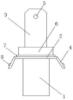
[0015] As attached figure 1 As shown, an oil alarm joint leakage prevention structure includes a connecting column 1, an insert 2 and a connecting piece 3. The characteristic is that the insert 2 is connected to the connecting column 1, and the insert 2 is provided with The socket 5, the connecting piece 3 is arranged between the connecting post 1 and the insert 2, a limit plate 4 is arranged on the connecting piece 3, and a connecting block 6 is arranged between the connecting post 1 and the insert 2, A connecting block 6 is provided between the connecting column 1 and the insert 2, and a sealing ring 7 is arranged between the connecting piece 3 and the connecting block 6. The connecting block 6 improves the sealing performance between the connecting column 1 and the insert 2 , Improve the leak-proof performance of the oil alarm joint, enhance the quality performance of the oil alarm joint, and then improve the product quality of the oil alarm. The sealing ring 7 further improv...

Embodiment 2

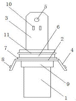
[0020] As attached figure 2 As shown, an oil alarm joint leakage prevention structure includes a connecting column 1, an insert 2 and a connecting piece 3. The characteristic is that the insert 2 is connected to the connecting column 1, and the insert 2 is provided with The socket 5, the connecting piece 3 is arranged between the connecting post 1 and the insert 2, a limit plate 4 is arranged on the connecting piece 3, and a connecting block 6 is arranged between the connecting post 1 and the insert 2, A connecting block 6 is provided between the connecting column 1 and the insert 2, and a sealing ring 7 is arranged between the connecting piece 3 and the connecting block 6. The connecting block 6 improves the sealing performance between the connecting column 1 and the insert 2 , Improve the leak-proof performance of the oil alarm joint, enhance the quality performance of the oil alarm joint, and then improve the product quality of the oil alarm. The sealing ring 7 further impr...


PUM


Abstract

The invention provides an anti-leakage structure for a joint of an engine oil alarm, which includes a connecting column, an insertion piece and a connecting piece. The connecting piece is arranged between the connecting post and the inserting piece, a limiting plate is arranged on the connecting piece, and a connecting block is arranged between the connecting post and the inserting piece. In the present invention, a connecting block is arranged between the connecting column and the inserting piece, and a sealing ring is arranged between the connecting piece and the connecting piece. The sealing performance between the connecting column and the inserting piece is improved through the connecting block, and the joint of the oil alarm is improved. The anti-leakage performance enhances the quality and performance of the oil alarm joint, thereby improving the product quality of the oil alarm. The sealing ring further improves the sealing between the connecting column and the insert, and enhances the quality and performance of the oil alarm joint.

Description

Technical field [0001] The invention relates to the processing technical field of an oil alarm, in particular to an anti-leakage structure of an oil alarm joint. Background technique [0002] In the existing oil alarms, the inserts and connectors of the oil alarm connector are mostly split structures, so that there is a gap between the inserts of the oil alarm connector and the connector, resulting in the sealing performance of the oil alarm connector Poor, it may even cause a decline in the quality of the oil alarm product. After using for a period of time, the gap between the insert and the connecting piece may cause leakage of the oil alarm connector, shortening the service life of the oil alarm. Summary of the invention [0003] The purpose of the present invention is to overcome the problems of poor sealing performance, reduced product quality, and short service life of the oil alarm due to the gap between the insert and the connecting piece of the existing oil alarm joint, ...

Claims


Application Information

Patent Timeline
Patent Type & Authority Applications(China)
IPC IPC(8): H01R13/73H01R13/40H01R13/52
CPCH01R13/73H01R13/40H01R13/52H01R13/521
Inventor 乔斌李激
Owner 芜湖瑞德机械科技有限公司
Why Eureka
Try Eureka