Linearization Solution Method of Interval Reactive Power Optimization Model

An optimization model and linearization technology, applied in reactive power compensation, design optimization/simulation, instruments, etc., can solve problems such as long calculation time, inability to guarantee the convergence of iterative algorithms, and inability to achieve engineering practicality.

Active Publication Date: 2020-04-07
SOUTH CHINA UNIV OF TECH
View PDF1 Cites 0 Cited by
  • Summary
  • Abstract
  • Description
  • Claims
  • Application Information

AI Technical Summary

Problems solved by technology

However, the convergence of the iterative algorithm it uses cannot be guaranteed, and the calculation time is too long to achieve real engineering practicality.

Method used


Image

  • Linearization Solution Method of Interval Reactive Power Optimization Model
  • Linearization Solution Method of Interval Reactive Power Optimization Model
  • Linearization Solution Method of Interval Reactive Power Optimization Model

Examples


Embodiment

[0066] In order to facilitate understanding of the present invention, the following will be described in conjunction with the accompanying drawings.

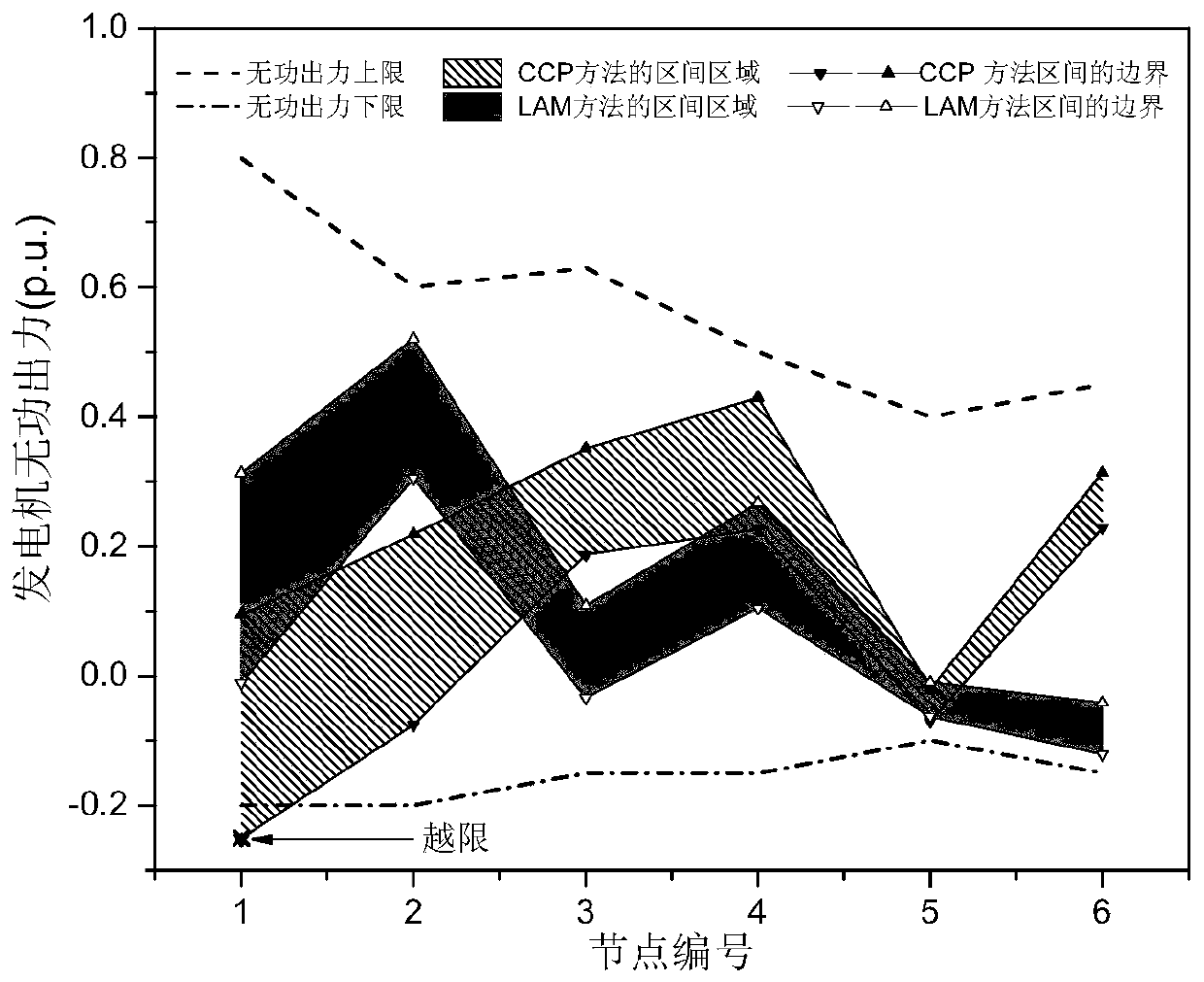
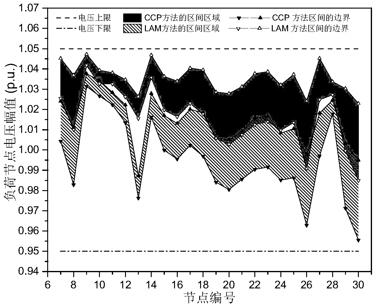
[0067] The modified IEEE30 node system is used for testing. The system has 37 transmission lines, 4 transformers, 1 reactive power compensation point, 6 generating units (No. 1 is a balancing unit), and 24 load nodes. Assuming that the active output and load of all generators have a fluctuation range of ±30%, the calculation of the parameters adopts the standard unit system, and the reference power is 100M V·A. For the convenience of drawing, we renumbered the nodes of the system. Among them, No. 1 is the balance node, No. 2-6 is the ordinary generator node, and No. 7-30 load nodes. The original order of the nodes of the same type remains unchanged .

[0068] The algorithm steps of the power flow calculation in the Cartesian coordinate interval are described in detail below:

[0069] The first step is to read the data of the s...


PUM


Abstract

The invention discloses an interval power flow calculation method in rectangular coordinate form based on linear programming. The method comprises the following steps: 1) establishing an interval reactive power optimization model: enabling both active output of an electric generator and load to be expressed in the form of an interval, and then, substituting the active output and load into a power flow equation in a certainty reactive power optimization model to obtain the interval reactive power optimization model; 2) classifying variables in the interval reactive power optimization model into two classes, one class of variable is a control variable capable of being controlled manually, and the other class of variable is a status variable changing with the control variable; 3) constructing a linear iterative model of the interval reactive power optimization model; 4) solving a linearized model for line interval reactive power optimization through a simplex method, and carrying out iteration repeatedly; and 5) outputting a result. The method has the advantages of being good in convergence, capable of ensuring that the obtained reactive power voltage control strategy completely meets security constraints for grid operation and high in efficiency and the like.

Description

technical field [0001] The present invention relates to a method for solving uncertain reactive power optimization problems in electric power systems. When solving reactive power optimization problems involving uncertain parameters, the method expresses uncertain parameters as intervals and assumes that all variables are is continuous, the optimal solution of the model is approached by the stepwise linearization method, and the optimal solution that truly satisfies the constraints of the uncertain reactive power optimization problem is obtained. Background technique [0002] The power system itself contains many uncertain factors, such as frequently changing commercial and residential loads, wind power, photovoltaic unit output that is difficult to predict accurately, and measurement errors of electrical parameters. The existence of these uncertain factors makes various optimal power flow models established based on grid parameters uncertain, while traditional deterministic ...

Claims


Application Information

Patent Timeline
Patent Type & Authority Patents(China)
IPC IPC(8): H02J3/16G06F30/20G06Q10/04G06Q50/06G06F113/04
CPCG06Q10/04G06Q50/06G06F30/20H02J3/16H02J2203/20Y02E40/30Y02E40/70Y04S10/50
Inventor 张聪陈皓勇
Owner SOUTH CHINA UNIV OF TECH
Why Eureka
Try Eureka