
Image forming apparatus

An image and structured technology, applied in the field of image forming devices

Active Publication Date: 2017-09-05
BROTHER KOGYO KK
View PDF15 Cites 0 Cited by
  • Summary
  • Abstract
  • Description
  • Claims
  • Application Information

AI Technical Summary

Problems solved by technology

the processing unit is configured to form a developer image on the sheet

Method used


Image

  • Image forming apparatus
  • Image forming apparatus
  • Image forming apparatus

Examples


Embodiment Construction

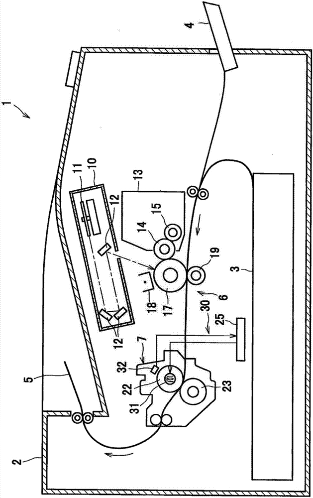
[0034] Next, according to an embodiment, a laser printer 1 as an image forming apparatus will be described with reference to the drawings.

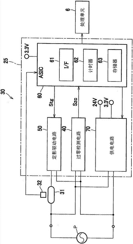
[0035] The laser printer 1 is configured to form an image on a sheet of paper 5 . Such as figure 1 As shown, the laser printer 1 is provided with a main body casing 2 , a sheet feed tray 3 , a manual insertion tray 4 , a process unit 6 and a fixing unit 7 . The main body casing 2 accommodates therein a sheet feed tray 3 , a part of the manual insertion tray 4 , a process unit 6 and a fixing unit 7 . A sheet of paper 5 is inserted from a selected one of the sheet feed tray 3 and the manual insertion tray 4, and is figure 1are shipped in the shipping direction indicated by the arrows in the description. The sheet-shaped paper 5 is discharged from the laser printer 1 through the processing unit 6 and the fixing unit 7 . The sheet-shaped paper 5 is an example of the "sheet".

[0036] The process unit 6 is configured to form a developer i...


PUM


Abstract

An image forming apparatus includes a process unit, a controller, and a fixing unit including a heater. The process unit is configured to form a developer image on a sheet. The heater is configured to be applied with an AC voltage, and to heat the sheet to thereby fix the developer image to the sheet. The controller is configured to perform: executing a continuous supply control in which the heater is continuously energized; acquiring an initial voltage dropping level of the AC voltage and a recovery time during the executing the continuous supply control; and setting a power supply control to control energization of the heater for starting up the heater on the basis of the acquired initial voltage dropping level and the acquired recovery time.

Description

technical field [0001] The present disclosure relates to an image forming apparatus capable of suppressing adverse effects applied to an AC power supply connected to the apparatus. The present disclosure also relates to a method for controlling the device so as to suppress this effect. Background technique [0002] Electrophotographic image forming apparatuses provided with heaters for thermally fixing developer images are well known in the art. In order to thermally fix the developer image, a heater heats the sheet-like paper on which the developer image has been transferred. Since a large power is required for heater operation, when the heater is activated, a large inrush current suddenly flows into the heater from a power source connected to the image forming apparatus. This large inrush current can cause the power supply voltage (ie, the voltage level of the power supply) to drop or drop. The voltage drop of the power supply voltage exerts an adverse effect not only o...

Claims


Application Information

Patent Timeline
Patent Type & Authority Applications(China)
IPC IPC(8): G03G15/20G03G15/00
CPCG03G15/205G03G15/5004G03G15/2039G03G15/80G03G15/2053
Inventor 矢田尚也
Owner BROTHER KOGYO KK
Learn More