
Grid driving circuit

A gate drive circuit and potential technology, which is applied in electrical digital data processing, instruments, computing, etc., can solve the problems of large width, disadvantageous narrow frame, and large frame area of ​​touch display panel.

Inactive Publication Date: 2017-09-05
SHANGHAI AVIC OPTOELECTRONICS
View PDF4 Cites 4 Cited by
  • Summary
  • Abstract
  • Description
  • Claims
  • Application Information

AI Technical Summary

Problems solved by technology

In this regard, the gate drive circuit of the existing touch display panel usually adopts the method of additionally adding control electrode lines to be electrically connected to the output terminals of the scanning units corresponding to each gate line, so as to realize the potential of each gate line in the touch detection stage. However, due to the large number of gate lines in the touch display panel, the length and width of the electrical connection lines electrically connected to the scanning units corresponding to some gate lines in the gate drive circuit are relatively long, thus As a result, the border area of ​​the touch display panel is relatively large, which is not conducive to the realization of a narrow border

Method used


Image

  • Grid driving circuit
  • Grid driving circuit
  • Grid driving circuit

Examples


Embodiment Construction

[0189] The following will clearly and completely describe the technical solutions in the embodiments of the present invention with reference to the accompanying drawings in the embodiments of the present invention. Obviously, the described embodiments are only some, not all, embodiments of the present invention. Based on the embodiments of the present invention, all other embodiments obtained by persons of ordinary skill in the art without making creative efforts belong to the protection scope of the present invention.

[0190] In the following description, a lot of specific details are set forth in order to fully understand the present invention, but the present invention can also be implemented in other ways different from those described here, and those skilled in the art can do it without departing from the meaning of the present invention. By analogy, the present invention is therefore not limited to the specific examples disclosed below.

[0191]An embodiment of the pres...


PUM


Abstract

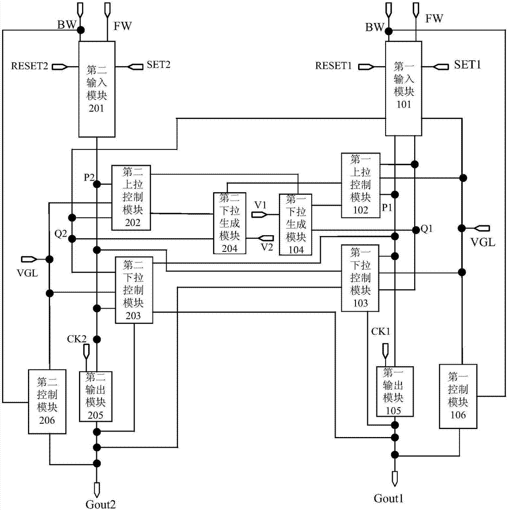
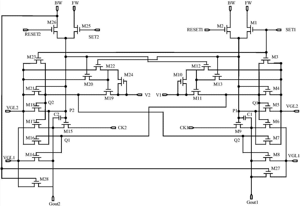
The invention discloses a grid driving circuit. In a display stage, in response to a low potential of a second voltage end, first and second control modules disconnect a third voltage end from a first output end; in a touch control stage, in response to a high potential of the second voltage end, the first and second control modules connect the third voltage end with the first output end; and thus, each scanning unit is provided with the first and second control modules, in the touch control stage, the first control module keeps the first output end in the low potential and the second control module keeps a second output end in the low potential, so that a capacitive coupling effect between grid lines and touch control electrodes in a touch control display panel used by the grid driving circuit is weakened, the precision of touch control detection is improved, added lines are short and narrow, an occupied frame is small in the area, and a narrow frame can be realized.

Description

technical field [0001] The present invention relates to the technical field of display driving, in particular to a gate driving circuit. Background technique [0002] With the development of display technology, more and more display panels are integrated with touch function, and its touch principle is divided into mutual capacitance touch technology and self-capacitance touch technology, wherein, the self-capacitance touch technology is due to The mutual capacitance touch technology only needs one layer of touch electrodes, which is more suitable for the development of thinner and thinner display panels. [0003] At present, the self-capacitive touch display panel divides the common electrode layer in the display panel into multiple common electrode units, adopts a time-sharing driving method, and multiplexes the common electrode units into touch electrode units to further reduce the The thickness of the display panel also improves the production efficiency and reduces the ...

Claims


Application Information

Patent Timeline
Patent Type & Authority Applications(China)
IPC IPC(8): G09G3/20G06F3/041
CPCG09G3/20G06F3/0416G09G2310/0267
Inventor 金慧俊
Owner SHANGHAI AVIC OPTOELECTRONICS
Learn More