Sliding type micro limit general switch
A sliding and position-limiting technology, which is applied in the direction of electric switches, contacts, electrical components, etc., can solve the problems of non-energized switch signals, flickering, and inability to withstand current, so as to increase the metal conductive cross-sectional area, improve the safety factor, Meet the effect of industry use
- Summary
- Abstract
- Description
- Claims
- Application Information
AI Technical Summary
Problems solved by technology
Method used
Image
Examples
Embodiment 1
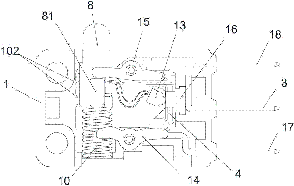
[0030] Such as figure 1 and Figure 8 As shown, the sliding type micro limit universal switch of the present invention includes a bottom case 1 and a face cover 101, and a working component arranged between the bottom case 1 and the face cover 101, and the working component is arranged in the groove of the bottom case 1 Inside.
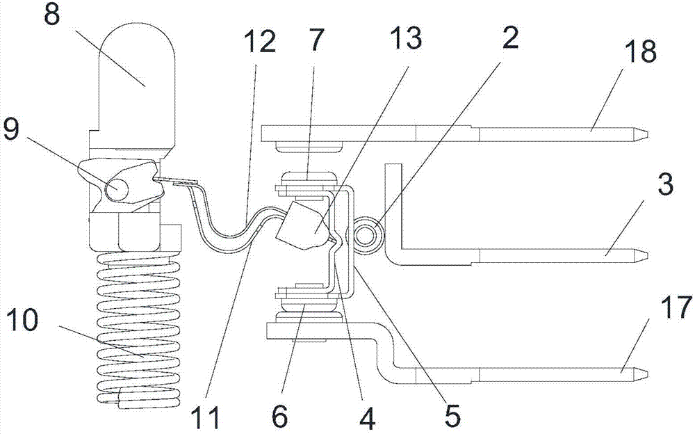
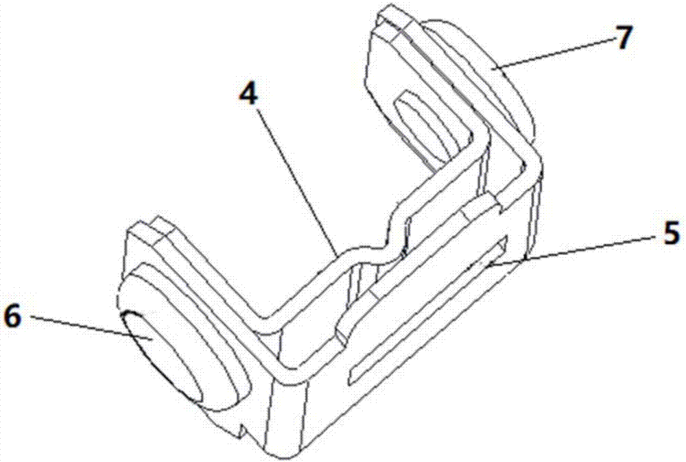
[0031] Such as Figure 1-3 As shown, the working assembly includes a movable contact piece assembly, a movable assembly, a movable rod assembly, a rolling element 2, a common pin 3 and a connecting pin assembly; the moving contact piece assembly includes a movable assembly support 4, a rolling element contact 5, A contact 6 and a second contact 7, the ends of the movable component support 4 and the rolling body contact 5 are fixed together by the first contact 6 and the second contact 7 respectively. The movable assembly support 4 is provided with a groove, and one end of the movable assembly is pressed against the groove of the movable assembly su...
Embodiment 2
[0040] like Figure 11 As shown, the main difference between the present embodiment and the first embodiment is that the movable assembly is changed to a single shrapnel structure, that is, only one main shrapnel 11 is formed, and the structure of other components remains unchanged, and the function of the main shrapnel 11 is the same as that of the first embodiment. In the first embodiment, there are two ways to solve the problem of power failure or flickering in the critical position of the switch. One is: when approaching the trigger position of the switch, the rotating block 9 is in contact with the boss 102 of the bottom shell. Compared with the movable assembly, the rotating block 9 and the movable contact piece assembly reach the force balance position first and rotate, and the rotating block 9 rotates The momentary movable component and the movable contact component form an angle, so as to avoid the force balance between the movable component and the movable contact co...
PUM
 Abstract
Description
Claims
Application Information
 - R&D
- Intellectual Property
- Life Sciences
- Materials
- Tech Scout
- Unparalleled Data Quality
- Higher Quality Content
- 60% Fewer Hallucinations
Browse by: Latest US Patents, China's latest patents, Technical Efficacy Thesaurus, Application Domain, Technology Topic, Popular Technical Reports.
© 2025 PatSnap. All rights reserved.Legal|Privacy policy|Modern Slavery Act Transparency Statement|Sitemap|About US| Contact US: help@patsnap.com


