Sliding micro limit general switch

A sliding and position-limiting technology, which is applied in the direction of electric switches, contacts, and contact electrical connections, can solve the problems of non-energized switch signals, inability to withstand current, flickering, etc., to increase the metal conductive cross-sectional area and meet the needs of the industry. Use, work safe and reliable effect

Active Publication Date: 2019-04-30
ZHANGZHOU JUANMEI ELECTRIC TECH CO LTD
View PDF7 Cites 0 Cited by
  • Summary
  • Abstract
  • Description
  • Claims
  • Application Information

AI Technical Summary

Problems solved by technology

However, the structural size of the micro switch itself is small, resulting in a small cross-sectional area of ​​the conductive metal sheet, which cannot withstand a large current, and it is easy to burn out when used in a situation that requires a large current
In addition, in the action mode of the existing micro switch, there is a force balance between the conductive metal sheet during the switching process of normally open and normally closed, which leads to the fact that the normally open or normally closed connectors are not energized at the critical position of the switch. Or there is a phenomenon that the switch signal flickers

Method used


Image

  • Sliding micro limit general switch
  • Sliding micro limit general switch
  • Sliding micro limit general switch

Examples


Embodiment 1

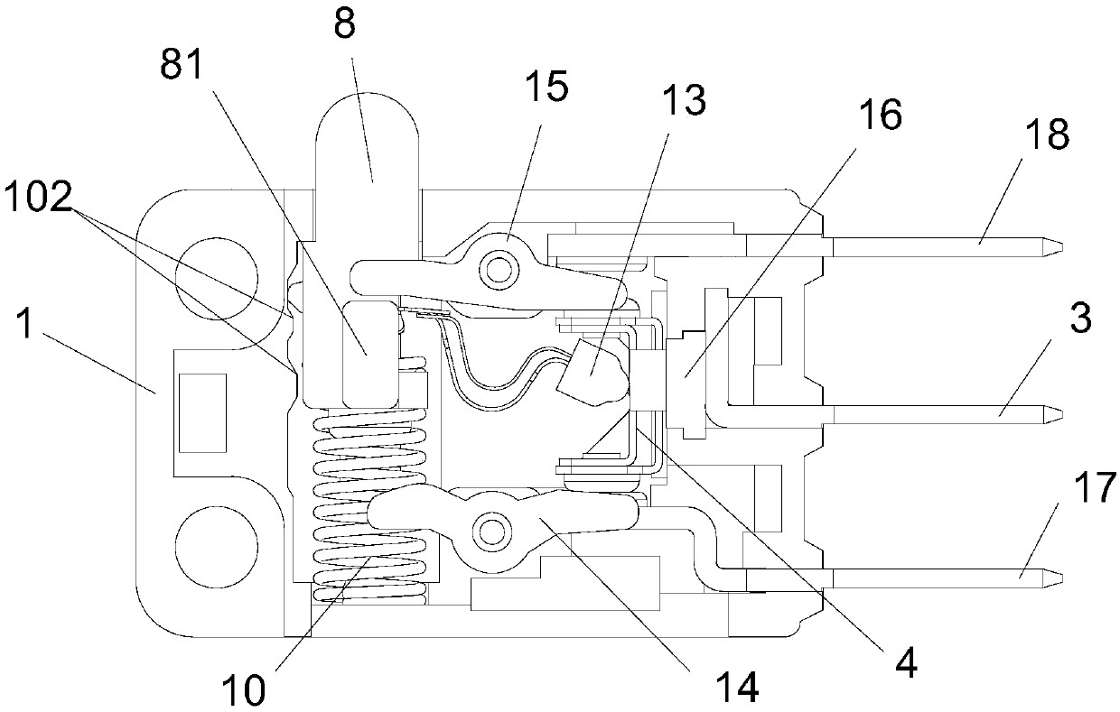
[0030] like figure 1 and Figure 8 As shown, the sliding type micro limit universal switch of the present invention includes a bottom case 1 and a face cover 101, and a working component arranged between the bottom case 1 and the face cover 101, and the working component is arranged in the groove of the bottom case 1 Inside.

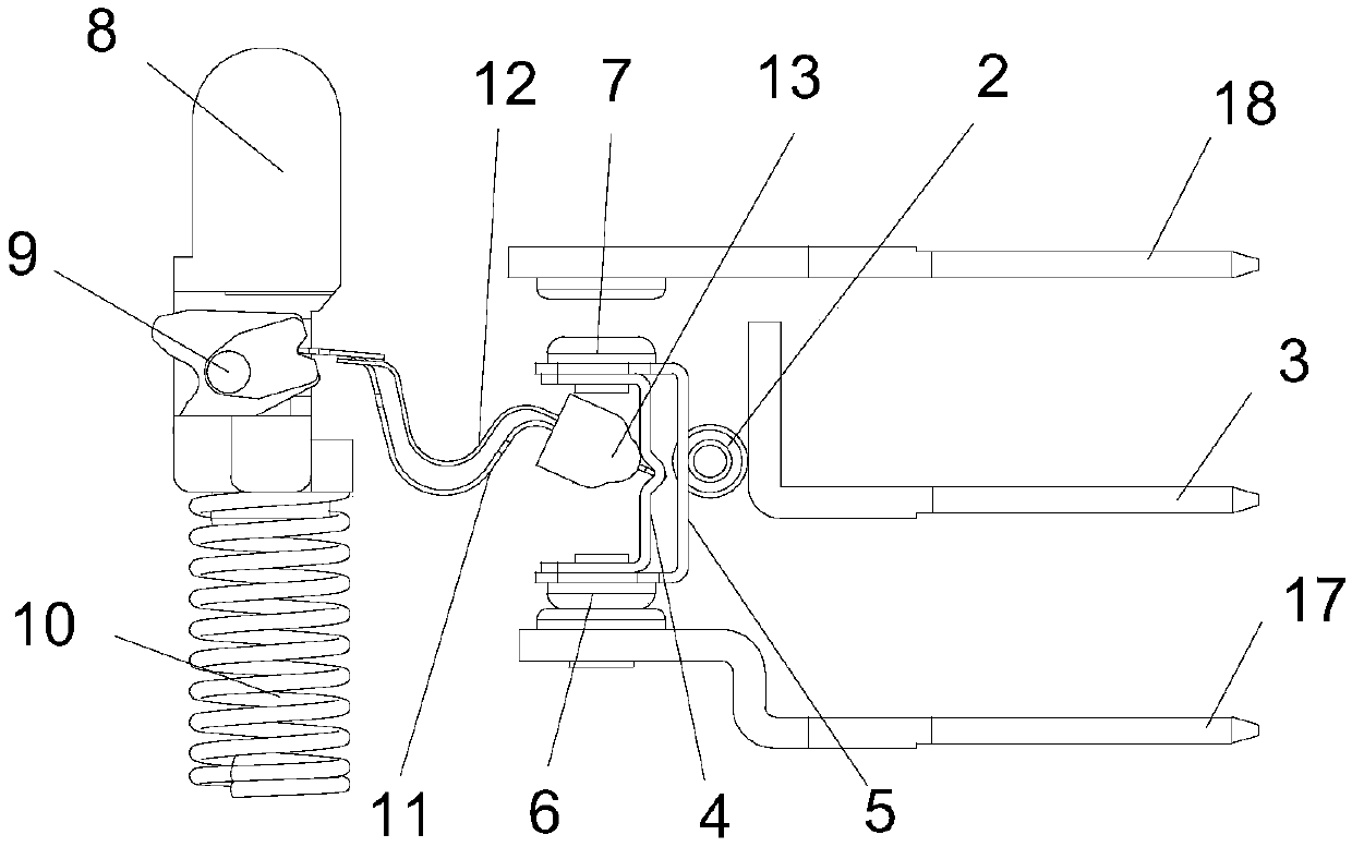
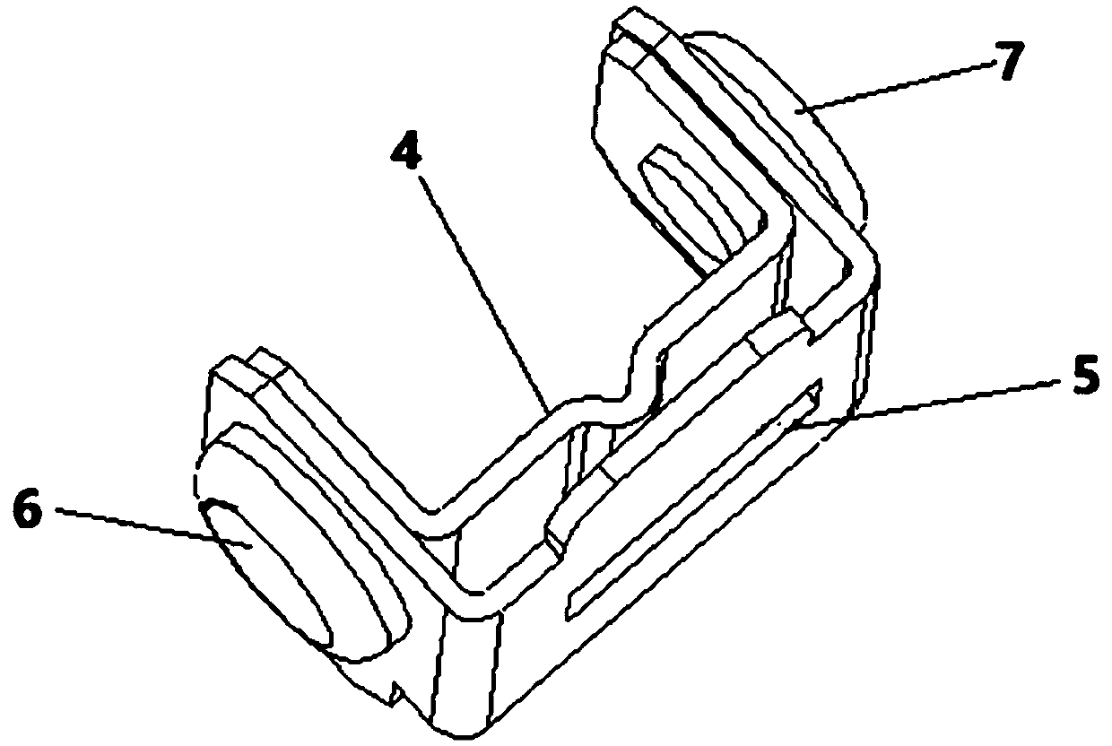
[0031] like Figure 1-3 As shown, the working assembly includes a movable contact piece assembly, a movable assembly, a movable rod assembly, a rolling element 2, a common pin 3 and a connecting pin assembly; the moving contact piece assembly includes a movable assembly support 4, a rolling element contact 5, A contact 6 and a second contact 7, the ends of the movable component support 4 and the rolling body contact 5 are fixed together by the first contact 6 and the second contact 7 respectively. The movable assembly support 4 is provided with a groove, and one end of the movable assembly is pressed against the groove of the movable assembly support ...

Embodiment 2

[0040] like Figure 11 As shown, the main difference between this embodiment and the first embodiment is that the movable component is changed to a single-shrapnel structure, that is, there is only one main elastic piece 11, and the structure of the other components remains unchanged. In the first embodiment, there are two ways to solve the power failure or flickering phenomenon of the switch at the critical position. One is: when the trigger position of the switch is approached, the rotating block 9 is in contact with the bottom case boss 102, and the rotating block 9, compared with the movable assembly, first reaches the force balance position and rotates, and the rotating block 9 rotates. Instantaneously, the movable component and the movable contact piece form an included angle, so as to avoid the force balance between the movable component and the movable contact piece component, which may lead to the occurrence of power failure or flickering of the switch. The other is:...


PUM


Abstract

The invention discloses a sliding type micro limit general switch. The switch comprises a bottom casing, a surface cover and working assemblies arranged between the bottom casing and the surface cover; the working assemblies include a moving contact assembly, a movable assembly, a movable rod assembly, a roller, a public pin and a plug pin assembly; the two ends of the movable assembly compresses the moving contact assembly and the movable rod assembly respectively; the moving contact assembly keeps making contact with the roller under the pressure effect of the movable assembly, the roller keeps making contact with the public pin under the pressure effect of the moving contact assembly, the moving contact assembly makes contact and is electrically connected with the public pin via the roller, and the moving contact assembly can slide up and down under the thrust effect of the movable assembly; and the plug pin assembly can make contact with the end portion of the moving contact assembly. Thus, the switch is avoided from a power-off or flickering phenomenon in a critical position, the metal conductive sectional area is increased, heavier current can be born, and the switch is safer and more reliable.

Description

technical field [0001] The invention relates to a micro switch, in particular to a micro-movement limit universal switch with a combination structure of sliding contacts. Background technique [0002] The micro switch is a contact mechanism with a small contact interval and a snap action mechanism that performs switching actions with a specified stroke and a specified force. In the prior art, the action of the conductive metal sheet is controlled by the elastic force generated by the compression deformation of the metal single elastic sheet or the tension of the spring, so as to realize the switch between normally open and normally closed switches. However, the structural size of the micro switch itself is small, resulting in a small cross-sectional area of ​​the conductive metal sheet, which cannot withstand a large current, and is easy to burn out when used in a situation that requires a large current. In addition, in the action mode of the existing micro switch, there is...

Claims


Application Information

Patent Timeline
Patent Type & Authority Patents(China)
IPC IPC(8): H01H13/52H01H13/14H01H13/26H01H1/50H01H1/58
CPCH01H1/50H01H1/58H01H13/14H01H13/26H01H13/52
Inventor 戴四川
Owner ZHANGZHOU JUANMEI ELECTRIC TECH CO LTD
Why Eureka
Try Eureka