Locking device for bridge velocity limiting indicating board

A speed limit sign, locking device technology, applied in the directions of roads, road signs, traffic signals, etc., can solve the problems of cumbersome installation process, affecting work efficiency, slow replacement speed, etc., to reduce personnel operations, improve work efficiency, The effect of preventing accidental falling

Inactive Publication Date: 2017-09-08
王莹
View PDF4 Cites 6 Cited by
  • Summary
  • Abstract
  • Description
  • Claims
  • Application Information

AI Technical Summary

Problems solved by technology

[0002] More speed limit sign devices are installed on some bridges and roads. The main function is to ensure driving safety and reduce traffic accidents caused by speeding. The existing speed limit signs are generally installed by bolts. Or other fasteners to fix it on the support frame above the road, the installation process is more cumbersome, at the same time, the speed limit sign will be adjusted according to the change of the actual bridge road traffic conditions, so when adjusting and replacing the speed limit sign When using a disassembly tool, bolts or other fasteners need to be disassembled first, which has problems such as difficulty in replacement and slow replacement speed, which seriously affects work efficiency

Method used


Image

  • Locking device for bridge velocity limiting indicating board
  • Locking device for bridge velocity limiting indicating board
  • Locking device for bridge velocity limiting indicating board

Examples


Embodiment Construction

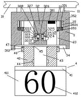
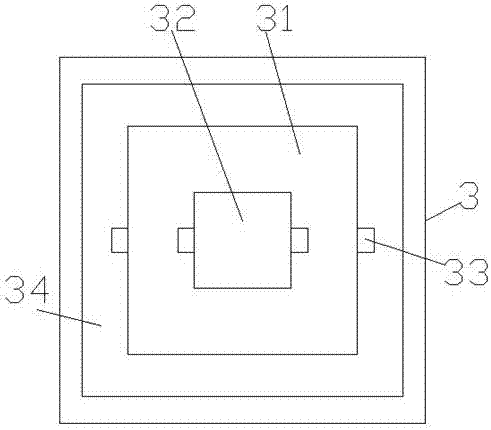
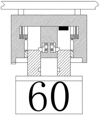
[0020] Such as Figure 1-Figure 6 As shown, a bridge speed limit indicator locking device of the present invention includes a base 3 and an indicator part 4 arranged below the base 3, and a suspension rod 10 is provided above the base 3, so that The base 3 is fixedly connected with the suspension rod 10 through the connecting rod 11, the base 3 is provided with a cavity 31, and the inner walls of the left and right sides of the cavity 31 are provided with first sliding grooves 33 in proportion, The top of the first sliding connection groove 33 is provided with a second sliding connection groove 35 on the side away from the cavity 31, and the second sliding connection groove 35 is provided with a sliding connection block 353 and slides with the sliding connection block 353. connected with the matching guide bar 351, the inner side of the sliding joint block 353 penetrates into the first sliding joint groove 33 and is slidably connected, and the bottom of the sliding joint block...


PUM


Abstract

The invention discloses a locking device for a bridge velocity limiting indicating board. The locking device comprises a base and an indicating board portion arranged below the base; a suspending rod is arranged above the base, the base and the suspending rod are fixedly connected through a connecting rod; a cavity is formed in the base; first slip grooves are symmetrically formed in the left and right sides of the cavity; a second slip groove is formed in one side, far from the cavity, of the top of the first slip groove; a slip block and a slide guide rod slidably matched with the slip block are arranged in the second slip groove; the inner side of the slip block penetrates through the first slip grooves and is in slip match; a locking piece is arranged in the bottom of the slip block in each of the first slip groove; a locking rod extending downward is arranged on the top wall in the cavity; left and right symmetrical locking cavities are formed in the lower side of the locking rod; a baffle plate is arranged between the left and right locking cavities; a third slip groove is formed in the top of each of the locking cavities; and a locking block is arranged in locking cavity. The locking device is simple in structure and convenient to mount and detach. The climbing time operation of staff is reduced, and the locking device is high in mounting stability and is unlikely to generate looseness.

Description

technical field [0001] The invention relates to the technical field of bridge facilities, in particular to a locking device for a bridge speed limit sign. Background technique [0002] More speed limit sign devices are installed on some bridges and roads. The main function is to ensure driving safety and reduce traffic accidents caused by speeding. The existing speed limit signs are generally installed by bolts. Or other fasteners to fix it on the support frame above the road. The installation process is more complicated. At the same time, the speed limit sign will be adjusted according to the actual bridge road traffic conditions. Therefore, it is necessary to adjust and replace the speed limit sign. When using a disassembly tool, bolts or other fasteners need to be disassembled first, which has problems such as difficulty in replacement and slow replacement speed, which seriously affects work efficiency. Contents of the invention [0003] The technical problem to be sol...

Claims


Application Information

Patent Timeline
Patent Type & Authority Applications(China)
IPC IPC(8): E01F9/615E01F9/658
Inventor 王莹
Owner 王莹
Why Eureka
Try Eureka