Safe welding device

A welding device and a safe technology, applied to the parts of the connecting device, coupling devices, welding accessories, etc., can solve the problems such as the lack of installation of the electric coupling slot, the power failure of the welding machine, and the electric shock hazard easily caused by the electric coupling head, so as to reduce the risk of electric shock. Electric shock accident, the effect of increasing safety and stability

Inactive Publication Date: 2017-09-08
冯斌斌
View PDF6 Cites 5 Cited by
  • Summary
  • Abstract
  • Description
  • Claims
  • Application Information

AI Technical Summary

Problems solved by technology

[0002] Welding is a manufacturing process and technology for joining metal or other thermoplastic materials by means of heating, high temperature or high pressure. It is widely used nowadays. Before using the welding machine, it is necessary to power on the welding machine so that the welding machine can operate normally. In places where many welding machines are used, a power supply frame is usually provided to supply power to the welding machine, but the electrical connection groove in the existing power supply frame is always in a power-on state, and the electrical connection groove is not provided with a coverable protective piece. It is easy to cause electric shock hazard when connecting the electric head. In addition, since the electric connection slot is not equipped with a lock for the electric connection head, if someone accidentally kicks and hits the power cord by mistake, it will cause a sudden power failure of the welding machine.

Method used


Image

  • Safe welding device
  • Safe welding device
  • Safe welding device

Examples


Embodiment Construction

[0021] The preferred embodiments of the present invention will be described in detail below in conjunction with the accompanying drawings, so that the advantages and features of the present invention can be more easily understood by those skilled in the art, so as to define the protection scope of the present invention more clearly.

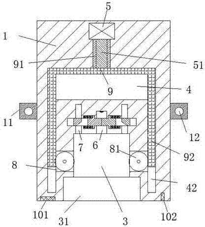
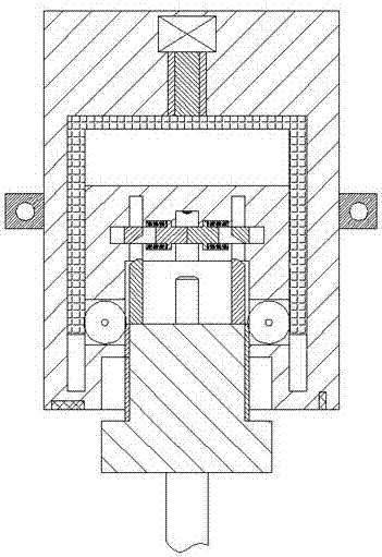
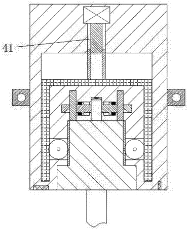
[0022] refer to Figure 1-6 A safe welding device shown includes a frame body 1 and an electrical joint head 2 inserted into the frame body 1 for matching connection. The lower ends of the left and right sides of the frame body 1 are fixedly equipped with fixing plates 11, The fixing plate 11 is provided with a fixing hole 12 penetrating up and down, and the fixing hole 12 is used to penetrate the screw so as to fix the frame body 1 firmly. The frame body 1 is provided with a card with the mouth forward Fixing groove 31, the rear end portion of described fixing groove 31 is provided with the inserting groove 3 that communicates with described fix...


PUM


Abstract

The invention discloses a safe welding device. The safe welding device comprises a frame body and an electric connector inserted in the frame body for matching connection, wherein fixed plates are fixedly mounted at the lower end parts of the left side and the right side of the frame body; a fixed hole which runs through up and down is formed in each fixed plate; a clamping groove is formed in the frame body, and an opening of the clamping groove is forward; an inserting groove communicating with the clamping groove is formed in the rear end part of the clamping groove; an electric connection groove communicating with the inserting groove is formed in the rear end part of the inserting groove; control grooves communicating with the inserting groove are symmetrically formed in the frame body on the left side and the right side of the electric connection groove; sealing devices for sealing the electric connection groove are further symmetrically formed in the frame body on the left side and the right side of the electric connection groove; a sliding groove is further formed in the frame body; and a pipe barrel cavity extending backwards is arranged at the middle part of the rear end part of the sliding groove. The safe welding device is simple in structure, safe and stable in power supply and safe and reliable in overall operation, the accidents of electric shocks in daily life are effectively reduced, and the device is applicable for popularization and application.

Description

technical field [0001] The invention relates to the field of welding, in particular to a safe welding device. Background technique [0002] Welding is a manufacturing process and technology for joining metal or other thermoplastic materials by means of heating, high temperature or high pressure. It is widely used nowadays. Before using the welding machine, it is necessary to power on the welding machine so that the welding machine can operate normally. In places where many welding machines are used, a power supply frame is usually provided to supply power to the welding machine, but the electrical connection groove in the existing power supply frame is always in a power-on state, and the electrical connection groove is not provided with a coverable protective piece. It is easy to cause electric shock hazard when connecting the electric head. In addition, because the electric connection slot is not equipped with a lock for the electric connection head, if someone accidentally...

Claims


Application Information

Patent Timeline
Patent Type & Authority Applications(China)
IPC IPC(8): H01R13/447H01R13/629H01R13/627B23K9/32
CPCH01R13/447B23K9/32H01R13/6275H01R13/629
Inventor 冯斌斌
Owner 冯斌斌
Why Eureka
Try Eureka