Electric pencil peeling device

一种削笔器、电动的技术,应用在削尖装置、印刷、办公用品等方向,能够解决影响电动削笔机正常工作性能、电机处于通电状态、无法保证刨削性能等问题,达到提高连接稳定性差、保证正常刨削、提高稳定性的效果

Active Publication Date: 2017-09-12
SUNWOOD HLDG GROUP
View PDF7 Cites 0 Cited by
  • Summary
  • Abstract
  • Description
  • Claims
  • Application Information

AI Technical Summary

Problems solved by technology

There is a shortcoming in this way of connecting the power supply: after the pencil is planed, the pen scraps produced need to be poured out, and the casing needs to be removed when pouring the pencil scraps. In this state, the planing component is It is directly exposed, and the user often forgets to unplug the power connector after planing, so the motor is always powered on, which may cut the user
However, due to different fields and actual working conditions, if this structure is directly applied to the electric pencil sharpener to realize automatic determination, it will affect the normal working performance of the electric pencil sharpener
This is mainly because the electric kettle is stationary when boiling water, while the electric pencil sharpener will vibrate when it is working. The vibration will cause a greater impact on the electrical connection when the split is set and cannot guarantee normal planing. sharpening performance, so it is not an option to set the electric pencil sharpener as a split structure to achieve automatic power-off

Method used


Image

  • Electric pencil peeling device
  • Electric pencil peeling device
  • Electric pencil peeling device

Examples


Embodiment 1

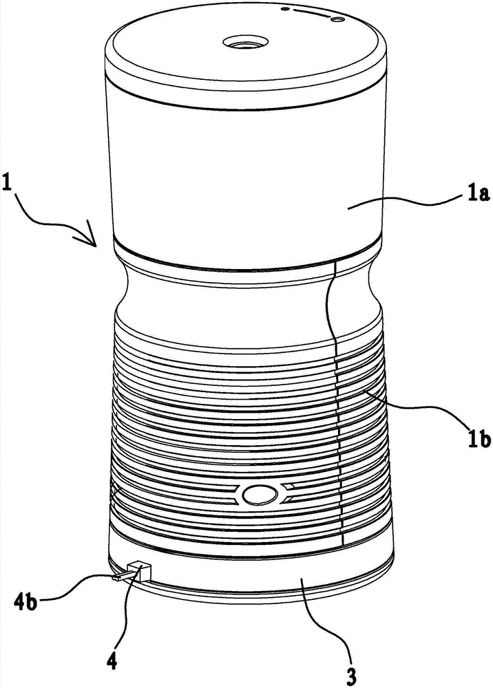
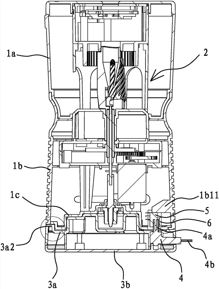
[0042] Such as figure 1 , figure 2 , Figure 5 , Figure 7 and Figure 8 As shown, an electric pencil sharpener includes a casing 1 and a pencil sharpening core 2 arranged in the casing 1. The casing 1 includes an upper casing 1a, a lower casing 1b, and a bottom cover 1c from top to bottom. , the lower end of the lower casing 1b is open, the bottom cover 1c is connected to the lower end of the lower casing 1b and closes the opening of the lower casing 1b, the upper part of the pencil sharpening movement 2 is located in the upper casing 1a, and the top of the pencil sharpening movement 2 The lower part is located in the lower housing 1b, and the lower end of the pencil sharpener movement 2 has several connecting posts, the pencil sharpener movement 2 and the bottom cover 1c are fixed by fasteners passing through the bottom cover 1c and penetrating into the connecting posts, and the pencil sharpener For the specific structure of the movement 2, reference may be made to the ...

Embodiment 2

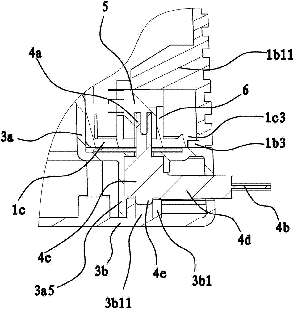
[0053] The structure and principle of this embodiment are basically the same as that of Embodiment 1, the difference is that in this embodiment, the positioning structure includes a connecting cavity arranged at the center of the bottom of the casing 1 and a raised matching part at the center of the upper end of the base 3 , the cross section of the fitting part is non-circular, the shape of the connecting cavity is the same as that of the fitting part and the fitting part is embedded in the connecting cavity.

[0054] Using a positioning structure formed by a non-circular mating portion and a connecting cavity with the same shape as the mating portion can also prevent the casing 1 from moving in the radial direction relative to the base 3 due to vibration, so as to improve the efficiency The problem of poor connection stability between the power connector 4 and the power connector 5 caused by automatic power-off during chip removal.


PUM


Abstract

The invention provides an electric pencil peeling device, belongs to the technical field of machinery, and aims to solve the problem that the existing electric pencil peeling device cannot automatically power off when pouring out pencil scraps. The electric pencil peeling device comprises a main case, wherein a power supply joint is fixed on the main case; the electric pencil peeling device further comprises a base; the main case is placed on the base; a power supply connector is fixed on the base and is electrically connected with the power supply joint; and a positioning mechanism for fixing the main case and the base in the circumferential direction is arranged between the main case and the base. The electric pencil peeling device has the advantages of capable of automatically powering off to ensure normal working performance when pouring out pencil scraps.

Description

technical field [0001] The invention belongs to the technical field of machinery and relates to an electric pencil sharpener. Background technique [0002] The electric pencil sharpener is also called the electric pencil sharpener. It is a very common office stationery in the office or daily study life. Today, with the accelerating pace of life, people are increasingly pursuing convenience and efficiency. The electric pencil sharpener has The function of automatically planing pencils is widely used by people. Various electric pencil sharpeners have appeared on the market at present, but its common structure generally includes a casing, and the pencil sharpener composed of a pen holder, a planing assembly and a motor that controls the work of the planing assembly is installed in the casing. core. For the power supply mode of the motor, electric pencil sharpeners are divided into two modes: battery-powered and connected to the power supply. The electric pencil sharpener powe...

Claims


Application Information

Patent Timeline
Patent Type & Authority Applications(China)
IPC IPC(8): B43L23/00
CPCB43L23/02B43L23/00
Inventor 林夏森
Owner SUNWOOD HLDG GROUP
Why Eureka
Try Eureka