Water conservancy facility

A facility and water conservancy technology, applied in mechanical equipment, pump control, components of pumping devices for elastic fluids, etc. The effect of resetting and installation work, improving the speed of disassembly and assembly, and improving work efficiency

Active Publication Date: 2017-09-15
HUAWEI TEHCHNOLOGIES CO LTD
View PDF7 Cites 7 Cited by
  • Summary
  • Abstract
  • Description
  • Claims
  • Application Information

AI Technical Summary

Problems solved by technology

In order to speed up water diversion, water diversion devices, such as water pumps, need to be installed at the mouths of some canals with small water level drops. However, such water diversion devices can only be used temporarily and cannot be installed in the canal for long-term use. They cannot meet the existing needs, and some areas will Install water diversion drums at the mouth of the channel to speed up the water flow through the rotating blades. However, these water diversion drums are mostly integrated structures, which are difficult to disassemble and have a single size, and cannot meet the needs of different water diversion volumes.

Method used


Image

  • Water conservancy facility
  • Water conservancy facility
  • Water conservancy facility

Examples


Embodiment Construction

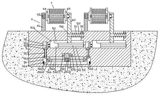
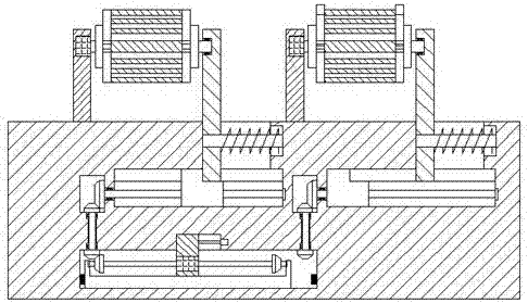
[0026] Such as Figure 1-Figure 8 As shown, a water conservancy facility of the present invention includes a main body 5 and a water diversion device 6 installed on the top of the main body 5 and arranged opposite to the left and right. The sliding connection column 63 on the right side and the water diversion drum 7 arranged between the column 61 and the sliding connection column 63, the main body 5 is provided with a guide cavity 54 extending left and right, and each of the The top of the guide cavity 54 is provided with transverse grooves 53 extending along the left and right sides of the top of the guide cavity 54, and the top of the extension section on the right side of each of the transverse grooves 53 is provided with a guide groove 51. A first sliding block 542 is connected to the cavity 54 by a sliding fit. The left side of the top of the first sliding block 542 is provided with a protruding block 531 extending into the transverse groove 53. The first sliding block 5...


PUM


Abstract

The invention discloses a water conservancy facility. The water conservancy facility comprises a body arranged on the bottom face of a canal, and water diversion devices arranged on the top of the body and oppositely arranged left and right. Each water diversion device comprises a vertical column arranged on the left side, a sliding connection column arranged on the right side, and a water diversion revolving drum arranged between the vertical column and the sliding connection column. Guiding connection cavities stretching left and right are oppositely formed in the body left and right. A transverse groove stretching along the left side and the right side of the top of each guiding connection cavity is formed in the top of the guiding connection cavity in a through penetrating manner. A guiding connection groove is formed in the top of the right stretching section of each transverse groove in a through penetrating manner. A first sliding connection block is connected into each guiding connection cavity in a sliding connection fit manner. A convex block stretching into the corresponding transverse groove is arranged on the left side of the top of each sliding connection block. A first screw rod stretching left and right is connected into each first sliding connection block in a screw thread fit manner. A transmission cavity is formed in the position, on the left side of each guiding connection cavity, of the body. The structure is simple, the flow rate of water flow is increased, water diversion irrigation is achieved, the arrangement speed is increased, equipment investment is reduced, and the manufacturing cost and the maintenance cost are reduced.

Description

technical field [0001] The invention relates to the technical field of water conservancy, and relates to a water conservancy facility. Background technique [0002] Water conservancy irrigation is one of the essential production links for agricultural production, especially in arid and rainless areas, efficient water conservancy irrigation equipment plays a vital role in improving crop yields. In order to speed up water diversion, water diversion devices, such as water pumps, need to be installed at the mouths of some canals with small water level drops. However, such water diversion devices can only be used temporarily and cannot be installed in the canal for long-term use. They cannot meet the existing needs, and some areas will A water diversion drum is installed at the mouth of the channel, and the water flow is accelerated through the rotating blades. However, these water diversion drums are mostly integrated structures, which are difficult to disassemble and have a sin...

Claims


Application Information

Patent Timeline
IPC IPC(8): F04D13/06F04D29/00F04D29/60F04D29/18F04D15/00
CPCF04D13/06F04D15/00F04D29/007F04D29/18F04D29/605
Inventor 黄俊凯
Owner HUAWEI TEHCHNOLOGIES CO LTD
Why Eureka
Try Eureka