Separable orthodontic bracket

An orthodontic bracket and separate technology, applied in the field of orthodontics, can solve problems such as narrow grooves, limited mouth opening of patients, and small lingual space

Inactive Publication Date: 2017-09-19
常州宁新医疗科技有限公司
View PDF0 Cites 2 Cited by
  • Summary
  • Abstract
  • Description
  • Claims
  • Application Information

AI Technical Summary

Problems solved by technology

This orthodontic system has the following problems: 1. The controllability of tooth movement in the early alignment process is poor, mainly because in the orthodontic process at this stage, the movement of the teeth mainly depends on the free sliding of the archwire within the range of the bracket. It is impossible to precisely control the movement direction and amount of the teeth, which easily leads to unpredictable tooth movements; 2. In the later fine adjustment process, the square archwire and the square groove cannot achieve close contact, and there is a certain gap between the archwire and the groove. If there is a gap, the bracket needs to be pre-set with an additional angle or an additional torque is added to the arch wire to make some compensation.
However, the orthodontic system still has the following problems: 1. The lingual fixed appliance still uses the sliding principle of the labial fixed orthodontic and the interaction between the square arch wire and the bracket to realize the three-dimensional direction control of the teeth, so there is also the above-mentioned labial The problem of fixed orthodontic treatment, and the lingual bracket is smaller than the labial bracket, the groove is narrower, and the movement in the three-dimensional direction is worse; 2. At the same time, the lingual space is small, and the patient's mouth opening is limited. Interfilament ligation is more complex than labial and thus requires more specialized training and chair time for the clinician
The orthodontic system based on the sliding mechanism of the arch wire is difficult to achieve precise control of the amount and mode of tooth movement

Method used


Image

  • Separable orthodontic bracket
  • Separable orthodontic bracket
  • Separable orthodontic bracket

Examples


Embodiment 1

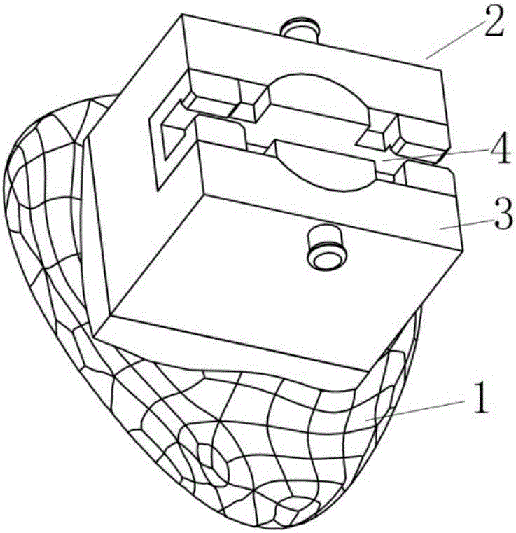
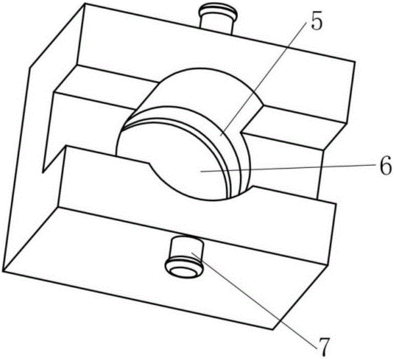
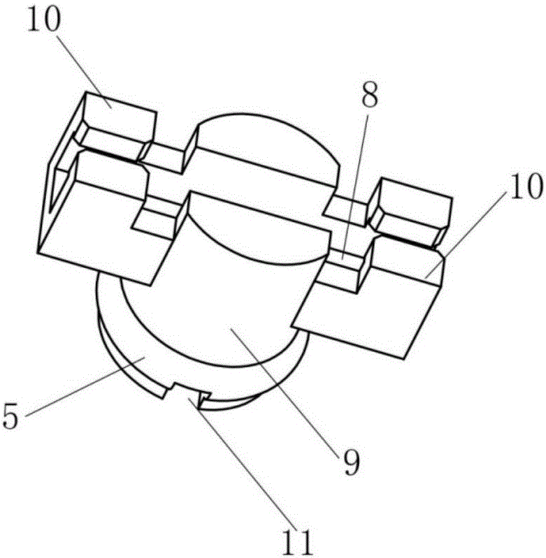
[0053] Embodiment 1: A detachable orthodontic bracket, specifically a lingual orthodontic bracket whose limiter is a cylinder, its structural diagram is as follows Figure 1-4 As shown, it includes a bracket bottom plate 1 and a bracket body 2 . The bracket body 2 includes a bracket retainer 3 , a bracket movable body 4 , and a fitting snap-in structure 5 arranged at corresponding contact positions of the bracket retainer 3 and the bracket movable body 4 . Wherein the bracket retainer 3 is provided with an opening cavity 6, and a traction hook 7 for ligation is provided on the gingiva maxillary; the bracket movable body 4 is provided with an archwire groove 8, a cylinder stopper 9, and Rigid clamping members 10 are arranged at both ends of the archwire groove 8, and grooves 11 are opened on the cylindrical limiter. The shape and size of the opening cavity 6 are set according to the shape and corresponding size of the bracket movable body 4 , and can accommodate the complete b...

Embodiment 2

[0058] Embodiment 2: A detachable orthodontic bracket, specifically a labial orthodontic bracket with a cuboid as the limiter, its structural schematic diagram is as follows Figure 5-7 As shown, including the bracket base plate and the bracket body. Wherein the bracket body includes a bracket retainer, a bracket movable body, and a fitting snap-in structure arranged at corresponding contact positions of the bracket retainer and the bracket movable body. Wherein the bracket bottom plate and the bracket retainer are integrally formed. The bracket retainer is provided with an opening cavity, whose shape and size are set according to the shape and corresponding size of the bracket movable body, and can accommodate the complete bracket movable body. The movable body of the bracket is provided with an arch wire groove and a cuboid stopper 13, and the opening direction of the arch wire groove is lingual, that is, facing the direction of the bracket retainer. Rigid clamping compone...

Embodiment 3

[0059] Embodiment 3: A bracket body of a detachable orthodontic bracket whose stopper is a trapezoidal body, its structural schematic diagram is as follows Figure 8-10 As shown, it includes a bracket retainer, a bracket movable body, and a pin connection structure 14 arranged at corresponding positions of the bracket retainer and the bracket movable body. The bracket retainer is provided with an opening cavity whose shape and size are set according to the shape and corresponding size of the bracket movable body, and can accommodate the complete bracket movable body. The movable body of the bracket is provided with an arch wire groove and a trapezoidal body limiting part 15 . Two pairs of elastic pieces 16 are arranged at both ends of the arch wire groove. The elastic sheet 16 can clamp the archwire through the elastic force, so that the preliminary positioning of the archwire and the movable body of the bracket is convenient for the operation of subsequent fixed connection m...


PUM


Abstract

The invention discloses a detachable orthodontic bracket, which belongs to the technical field of orthodontics. The detachable orthodontic bracket includes a bracket base plate and a bracket body, and the bracket body includes a bracket retainer, a bracket movable body and a connecting member, and the bracket retainer and the bracket The slot bottom plate is connected, the bracket movable body is connected with the arch wire, and the bracket retainer and the bracket movable body can realize detachable connection through the connecting member. The orthodontic bracket can accurately transmit the deformation amount of the prefabricated arch wire to the teeth, thereby precisely controlling the movement mode and amount of the teeth.

Description

technical field [0001] The invention relates to the technical field of orthodontics, in particular to an orthodontic bracket. Background technique [0002] Orthodontics is a discipline that treats misaligned teeth and tooth surface deformities through the application of orthodontic devices. At present, the most widely used bracket correction mainly includes fixed labial correction and customized lingual correction. [0003] Fixed labial correction is realized based on the interaction between the brackets bonded to the labial side and the sequence of arch wires, mainly including winged brackets (such as patent documents CN204446157U, CN2614644Y, CN202020559U), self-locking brackets (such as Patent documents CN104434324A, CN204636588U, CN201578387U), etc., in the early stage, the elasticity of the circular arch wire and the restriction of the orthodontic bracket to the arch wire were used to realize the teeth to slide freely according to the shape of the arch wire to achieve ...

Claims


Application Information

Patent Timeline
Patent Type & Authority Applications(China)
IPC IPC(8): A61C7/14
CPCA61C7/14
Inventor 赵宁钮叶新
Owner 常州宁新医疗科技有限公司
Why Eureka
Try Eureka