

Bulk cargo loading and unloading equipment and its balance boom system
A boom and balance technology, applied in cranes and other directions, can solve the problems of low movement stability and unstable internal force transmission, and achieve the effect of ensuring running stability and improving stability.
- Summary
- Abstract
- Description
- Claims
- Application Information
AI Technical Summary
Problems solved by technology
Method used
Image

Examples
Embodiment 1
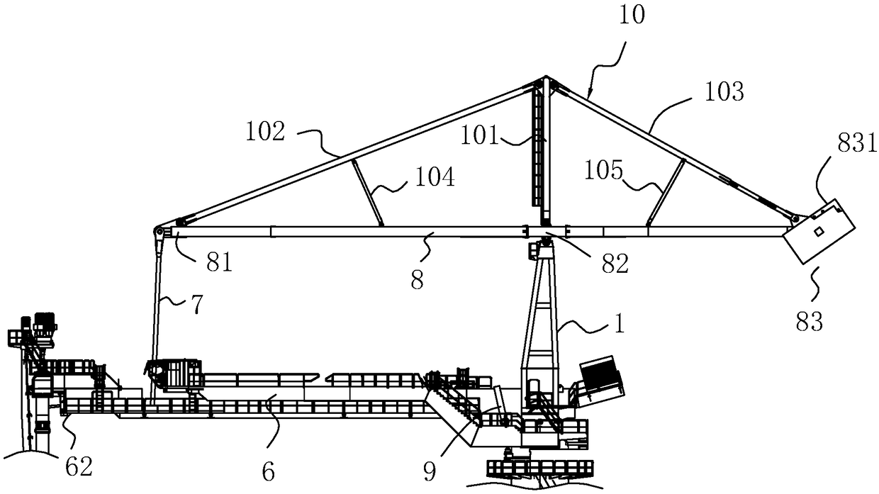
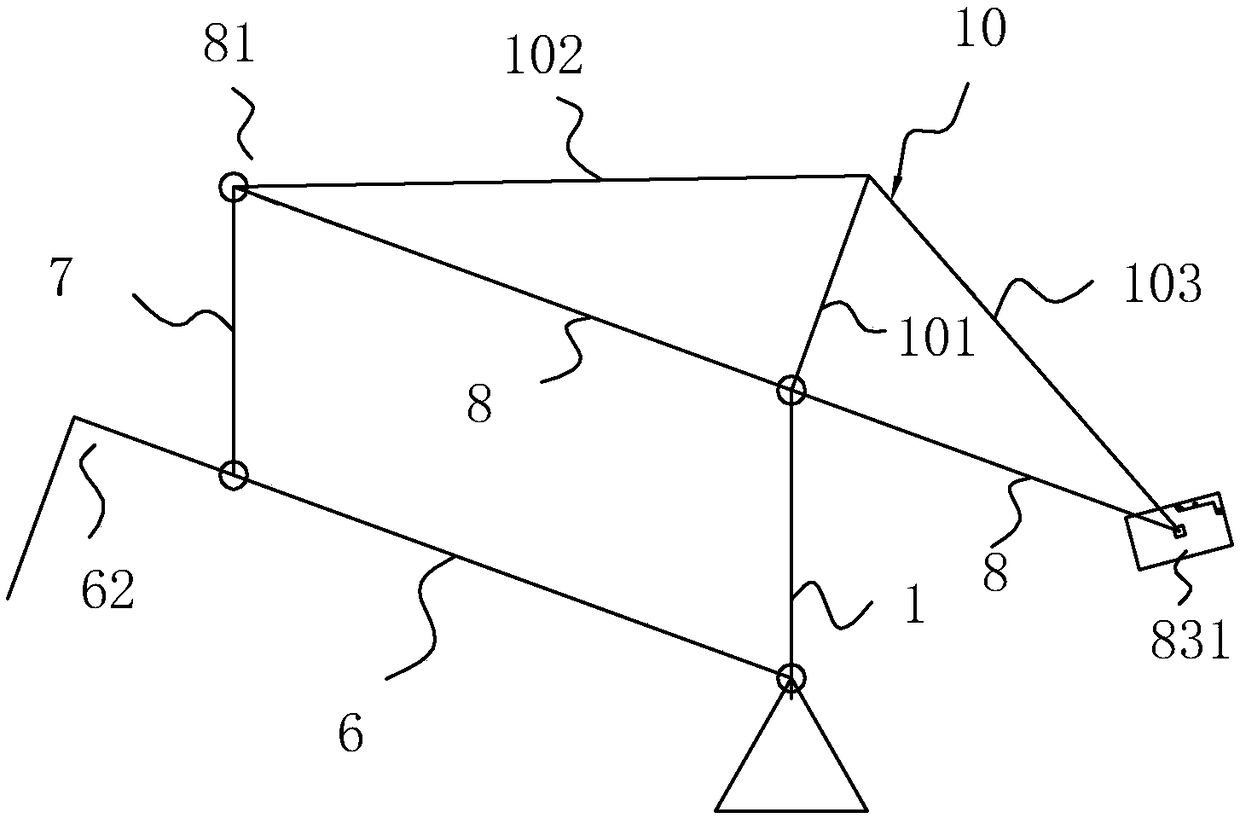
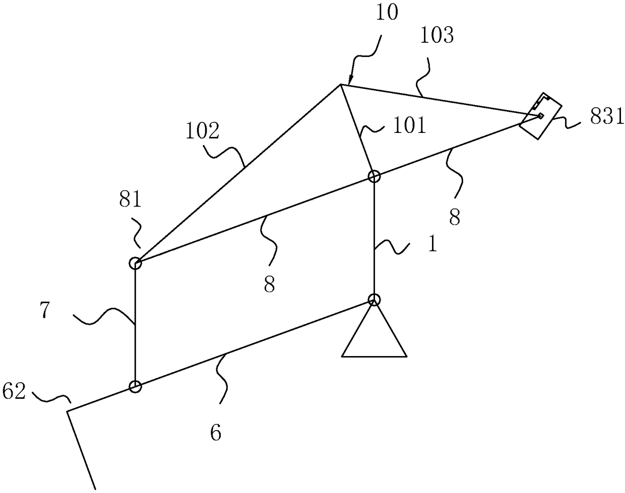
[0044] A balanced jib system, see figure 1 As shown, it includes a main support 1, a main arm 6, a connecting arm 7, a secondary arm 8, and a swing arm driving part 9, wherein the main support 1 is in a vertical state, and the main support 1 and the connecting arm 7 are parallel to each other. 6 and the auxiliary arm 8 are parallel to each other; one end of the main arm 6 is hinged to the main support 1, and the other end is a working end 62, and the corresponding working mechanism can be installed on the working end 62; the auxiliary arm 8 is located above the main arm 6, and the auxiliary arm 8 A secondary connecting end 81, a hinged end 82, and a load-bearing end 83 are sequentially arranged along the length direction. One end of the connecting arm 7 is hinged to the secondary connecting end 81, and the other end is hinged between the working end 62 of the main arm 6 and the hinge point. The hinged end 82 is hinged to the main support 1, and the weight 831 is installed on t...
Embodiment 2
[0049] A bulk cargo handling equipment, see Figure 4 As shown, it includes a frame 25, a turntable 2, and a rotary drive part 3. The turntable 2 is rotatably connected to the frame 25. The rotary drive part 3 can be a rotating motor, which drives the turntable 2 to rotate and the rotation axis of the turntable 2 is vertical. In the straight state, the balance jib system in the first embodiment is installed on the turntable 2, the main bracket 1 in the balance jib system is fixedly connected to the turntable 2, the main arm 6 is provided with a material transmission mechanism 5, and the working end 62 There is a vertical screw conveying mechanism 4; the rotary drive part 3 drives the turntable 2 to rotate in the circumferential direction, the swing arm drive part 9 drives the main arm 6 to swing up and down, and finally adjusts the position of the vertical bolt conveying mechanism at the working end 62, and the vertical screw conveys The mechanism 4 spirally transports the bul...
Embodiment 3
[0053] Compared with the second embodiment, the internal structure of the main support rod 11 is set differently, see Figure 6 as well as Figure 7 As shown, the main support rod 11 includes an active rod 12, a piston sleeve 13, and a driven rod 15; one end of the active rod 12 is hinged to the main arm 6, and the other end is an active piston end 121 that is sealed and slidably connected to the piston sleeve 13, In order to realize the sealing sliding connection, there is a sealing ring between the active piston end 121 and the inner wall of the piston sleeve 13, a one-way intake valve 22 is arranged on the active piston end 121, and the driven rod 15 is close to the end of the active rod 12 In order to be connected to the driven piston end 16 of the piston sleeve 13 for sealing sliding, in order to realize the sealing sliding connection, there is a sealing ring between the driven piston end 16 and the inner wall of the piston sleeve 13, and at the end of the piston sleeve 1...
PUM
 Abstract
Description
Claims
Application Information