
Practical electric fan device

A hair dryer, a practical technology, applied in the direction of the coupling device, the parts of the connecting device, the circuit, etc., can solve the problems of no locking device, affecting the use of the hair dryer, electric shock accidents, etc., to achieve convenient plug-in operation and reduce electric shock Accidents, the effect of eliminating electric shock accidents

Active Publication Date: 2017-09-26
吴江市民福电缆附件厂
View PDF3 Cites 0 Cited by
  • Summary
  • Abstract
  • Description
  • Claims
  • Application Information

AI Technical Summary

Problems solved by technology

[0002] After washing hair, people usually use a hair dryer to dry their hair. When using it, they will aim at the hair from all angles, so the angle of the hair dryer will also change. They are all connected by friction fit. Long-term plugging and unplugging are prone to loosening, and there is no other locking device, so when people use it, it is easy to pull the plug of the hair dryer from the socket, so that the power failure affects the use of the hair dryer, and The existing sockets connected to the hair dryer are all directly charged, so electric shock accidents are likely to occur when plugging the plug

Method used


Image

  • Practical electric fan device
  • Practical electric fan device
  • Practical electric fan device

Examples


Embodiment Construction

[0024] The preferred embodiments of the present invention will be described in detail below in conjunction with the accompanying drawings, so that the advantages and features of the present invention can be more easily understood by those skilled in the art, so as to define the protection scope of the present invention more clearly.

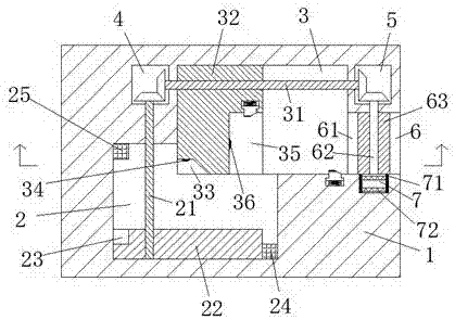
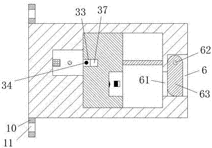
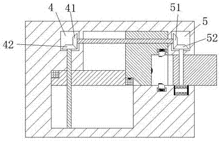
[0025] refer to Figure 1-8A practical hair dryer device shown includes a casing 1, a hanging arm 10 is fixedly arranged at the left part of the front and rear end faces of the casing 1, and a hanging hole 11 for screw insertion is arranged in the hanging arm 10. , the hanging hole in the hanging arm 10 is used to hang the shell 1, and the shell 1 is provided with a second sliding groove 2 and a first sliding groove at the rear end of the second sliding groove 2 3. The shell 1 at the left and right ends of the first sliding joint groove 3 is respectively provided with a left tooth joint groove 4 and a right tooth joint groove 5, and a sealing gro...


PUM


Abstract

The invention discloses a practical electric fan device which comprises a shell sleeve, wherein hanging arms are fixedly arranged at the left parts of the front and rear end surfaces of the shell sleeve; hanging holes allowing screws to penetrate are formed in the hanging arms; a second sliding connection groove and a first sliding connection groove which is formed in the rear end of the second sliding connection groove are formed in the shell sleeve; a left tooth connection groove and a right tooth connection groove are respectively formed in the shell sleeve at the left end and the right end of the first sliding connection groove; a sealing groove is formed in the right end surface of the shell sleeve; an insertion groove is communicated between the sealing groove and the first sliding connection groove; a left screw rod and a right screw rod which are propped into the left tooth connection groove and the right tooth connection groove and are in rotational matching connection with the shell sleeve are arranged in a rear part position of the first sliding connection groove. The practical electric fan device is simple in overall structure, relatively low in production cost and safe and stable in power supply.

Description

technical field [0001] The invention relates to the field of hair dryer equipment, in particular to a practical hair dryer device. Background technique [0002] After washing hair, people usually use a hair dryer to dry their hair. When using it, they will aim at the hair from all angles, so the angle of the hair dryer will also change. They are all connected by friction fit. Long-term plugging and unplugging are prone to loosening, and there is no other locking device, so when people use it, it is easy to pull the plug of the hair dryer from the socket, so that the power failure affects the use of the hair dryer, and Existing sockets connected to hair dryers are all directly charged, so electric shock accidents are likely to occur when inserting plugs. Contents of the invention [0003] The technical problem to be solved by the present invention is to provide a practical hair dryer device, which can solve the above-mentioned problems in the prior art. [0004] In order ...

Claims


Application Information

Patent Timeline
Patent Type & Authority Applications(China)
IPC IPC(8): H01R13/66H01R13/639H01R13/629H01R13/447
CPCH01R13/447H01R13/629H01R13/639H01R13/665
Inventor 石力峰
Owner 吴江市民福电缆附件厂
Learn More