Elevator hall door lighting device

A technology for door lights and elevators, which is applied in transportation, packaging, elevators, etc. It can solve the problems that hall door lights cannot be maintained and repaired, and achieve the effect of easy maintenance and repair operations and preventing design deterioration

Active Publication Date: 2019-05-21
MITSUBISHI ELECTRIC CORP
View PDF6 Cites 0 Cited by
  • Summary
  • Abstract
  • Description
  • Claims
  • Application Information

AI Technical Summary

Problems solved by technology

[0002] In the past, the hall door lights assembled on the door frame or landing wall could not be maintained and repaired from the landing side, but from the hoistway side.

Method used


Image

  • Elevator hall door lighting device
  • Elevator hall door lighting device
  • Elevator hall door lighting device

Examples


Embodiment approach 1

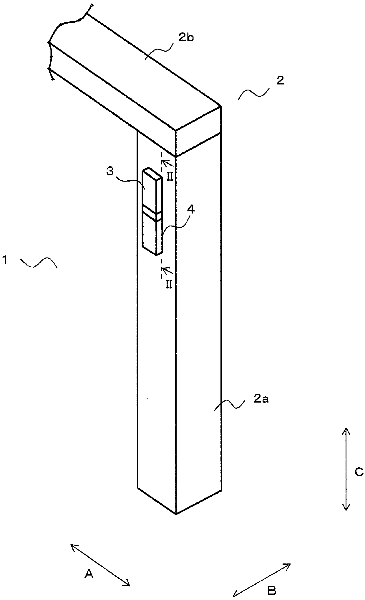
[0026] figure 1 It is a perspective view showing a part of an elevator hall doorway including the elevator hall light device according to Embodiment 1 of the present invention. Below, will figure 1 The direction of the arrow A of is set as the width direction of the landing entrance 1, figure 1 The direction of arrow B in is set as the depth direction of landing entrance 1, figure 1 The direction of the arrow C in is described as the height direction of the landing entrance 1.

[0027] Such as figure 1 As shown, a door frame 2 that is fixed to a hall wall (not shown) and surrounds three sides of the hall doorway 1 is provided at the hall doorway 1 . The door frame 2 has a pair of vertical frames 2a ( figure 1 Only one is shown in the figure); and the top frame 2b provided between the upper ends of the pair of vertical frames 2a.

[0028] One of the vertical frames 2a is provided with a hall light device 3 which notifies a user of the arrival of a car by lighting. When t...

Embodiment approach 2

[0073] In Embodiment 1 above, an example in which the hall light device 3 is provided in the center of the vertical frame 2 a in the width direction has been described. On the other hand, in this Embodiment 2, the example in which the hall light device 3 is provided in the corner part of the hall doorway 1 of the vertical frame 2a by the hall side is demonstrated.

[0074] Figure 5 It is a perspective view showing a part of an elevator hall entrance 1 including a hall light device 3 for an elevator according to the second embodiment. also, Figure 6 is showing Figure 5 An enlarged view of the structure of the hall door light device 3. also, Figure 7 is shown along Figure 6 A cross-sectional view of the hall door lamp device 3 observed on line VII-VII. and, Figure 8 is shown along Figure 6 A cross-sectional view of the hall door light device 3 viewed on line VIII-VIII. In addition, in Figure 6 , the landing wall 5 is not shown in the figure.

[0075] Such as F...

Embodiment approach 3

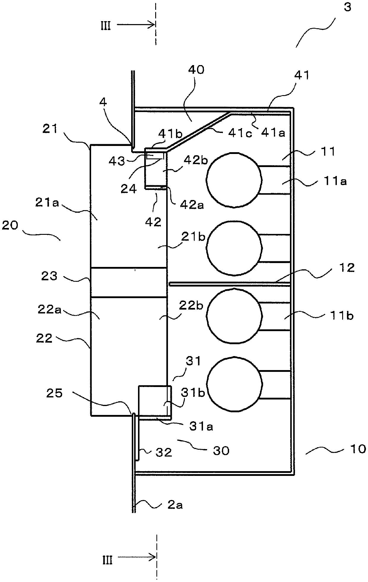
[0100] This third embodiment describes a modified example of the previous first embodiment. Figure 9 A vertical cross section of the hall light device 3 according to Embodiment 3 is shown. also, Figure 10 is shown along Figure 9 The sectional view of the hall door light device 3 observed on the X-X line of FIG. in addition, Figure 9 is equivalent to the previous embodiment 1 figure 2 diagram.

[0101] Such as Figure 9 and Figure 10 As shown, the housing 10 has fixed multiple ( Figure 9 4 in ) the base housing 101 of the illuminant 11 . The base case 101 has: a central surface 101a away from the opening 4 in the depth direction; an upper surface 101b protruding from the upper end of the central surface 101a toward the opening 4 in the height direction; The lower end portion of the lower surface 101c protrudes toward the opening 4 .

[0102] The respective light emitters 11 are arranged at a distance from each other in the height direction. In addition, each i...


PUM


Abstract

This hall lantern device for an elevator is equipped with: a housing (10) that covers, from the opposite side from a landing, an opening (4) provided to a vertical frame (2a) of a jamb (2) and has luminous bodies (11) therein; a display body (20) that closes the opening (4) and allows the light from the luminous bodies (11) to pass therethrough to the landing; a guide member (30) that is provided to the vertical frame (2a) and guides the display body (20) between a closed position, where the display body (20) closes the opening (4), and an open position, where the display body (20) is separated from the opening (4); and a holding mechanism (40) that keeps the display body (20) in the closed position. The display body (20) is provided with a recess (24) in which, in the closed position, the holding mechanism (40) is partially fitted. The position with the holding mechanism (40) partially fitted in the recess (24) can be released by a hold releasing member (50) that can be inserted into a gap provided between the opening (4) and the display body (20).

Description

technical field [0001] The present invention relates to a hall door light device of an elevator which is installed on a door frame of a landing and is maintained and overhauled from the landing side. Background technique [0002] In the past, hall door lights assembled on door frames or landing walls could not be maintained and repaired from the landing side, but from the hoistway side. Therefore, in order to perform maintenance and inspection work from the hall side, there is known a hall door lamp of an elevator in which an opening and closing panel having a light-transmitting lens embedded in the panel body is mounted on the vertical frame of the door frame through a hinge, and the opening and closing panel is In the open state, maintenance and inspection work can be performed from the hall side (for example, refer to Patent Document 1). [0003] In the hall door light disclosed in Patent Document 1, when the opening of the vertical frame is opened by moving the opening ...

Claims


Application Information

Patent Timeline
Patent Type & Authority Patents(China)
IPC IPC(8): B66B3/00
CPCB66B3/00
Inventor 藤原一彦石田敬近藤雅大松田和子
Owner MITSUBISHI ELECTRIC CORP
Why Eureka
Try Eureka