Disk brake apparatus for a railway vehicle

A disc brake and railway vehicle technology, applied in railway braking systems, railway car body components, brake types, etc., can solve the problem of driving disc brakes with complex structures, difficulty in performing maintenance and repair operations, and excessive manufacturing costs. problems, to achieve the effect of easy maintenance and repair operations, saving manufacturing costs, and simplifying the structure

Inactive Publication Date: 2015-07-01
YUJIN MACHINERY
View PDF7 Cites 0 Cited by
  • Summary
  • Abstract
  • Description
  • Claims
  • Application Information

AI Technical Summary

Problems solved by technology

[0013] This is due to the complexity of the structure used to drive the disc brake, which consumes too much manufacturing cost and is not easy to disassemble and assemble, resulting in the problem that it is difficult to perform maintenance and repair operations.

Method used


Image

  • Disk brake apparatus for a railway vehicle
  • Disk brake apparatus for a railway vehicle
  • Disk brake apparatus for a railway vehicle

Examples


Embodiment Construction

[0035] Hereinafter, a disc brake device for a railway vehicle according to the present invention will be described in detail with reference to the accompanying drawings.

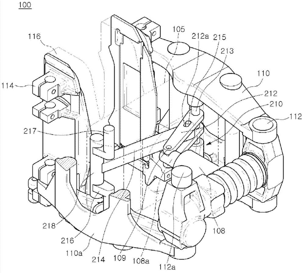
[0036] image 3 is a perspective view showing a disc brake device for a railway vehicle according to the present invention, Figure 4 is a side view showing a disc brake device for a railway vehicle according to the present invention, Figure 5 is a plan view showing a disc brake device for a railway vehicle according to the present invention, Figure 6 It is a figure which shows the fastening state of the connecting rod and an eccentric rod of this invention.

[0037] Such as Figure 3 to Figure 6 As shown, the disc brake device 100 for a railway vehicle of the present invention generates a braking force through a brake disc disposed on a wheel or an axle of a railway vehicle, and has a pair of caliper levers 110, 110a spaced apart from each other. A pair of caliper levers 110, 110a are arranged side by...


PUM


Abstract

The present invention relates to a disk brake apparatus for a railway vehicle, and more particularly, to a disk brake apparatus for a railway vehicle which is a brake apparatus installed on a railway vehicle and operated by using a lever mechanism so that: manufacturing costs thereof can be reduced due to the simplified structure of the apparatus; stopping force is increased due to easy lever adjustment; and maintenance and repair can be easily performed. To achieve the above objectives, the disk brake apparatus for a railway vehicle according to the present invention includes a pair of caliper levers actuated by the operation of a cylinder rod of the cylinder and a lever mechanism connected and coupled between the cylinder rod of the cylinder and the pair of caliper levers.

Description

technical field [0001] The present invention relates to a disc brake device for a railway vehicle, in more detail, relates to enabling the brake device installed on the railway vehicle to be activated by means of a lever mechanism, thereby simplifying the structure, saving manufacturing costs, and because the lever is easy to adjust Therefore, the braking force is improved, and the disc brake device for railway vehicles can be easily maintained and repaired. Background technique [0002] Generally, for a brake caliper unit of a disc brake device for a railway vehicle, a connecting rod is connected to a plurality of ends of a central caliper lever, and a braking force generating device and a brake provided between the ends of the caliper lever are connected to each other. The pneumatic cylinders are mutually expanded to perform braking work. [0003] In addition, it is known that a brake cylinder is connected to the central region of a plurality of caliper levers connected t...

Claims


Application Information

Patent Timeline
Patent Type & Authority Patents(China)
IPC IPC(8): B61H5/00F16D65/092F16D65/095F16D55/224
CPCF16D2125/28F16D65/38F16D55/2245F16D2121/02
Inventor 李宰荣
Owner YUJIN MACHINERY
Why Eureka
Try Eureka