
An expansion device for an earthquake-resistant buffer bridge

A telescopic device and bridge technology, applied in bridges, bridge construction, bridge parts, etc., can solve problems such as lack of shock absorption measures, small displacement adjustment range, and device damage, and achieve good displacement adjustment effects, diverse displacement adjustments, and protection The effect of internal components of the device

Inactive Publication Date: 2018-12-28
徐州霞光机械制造有限公司
View PDF4 Cites 0 Cited by
  • Summary
  • Abstract
  • Description
  • Claims
  • Application Information

AI Technical Summary

Problems solved by technology

Once the telescopic device is damaged, it will seriously affect the speed, comfort and safety of driving, and even cause driving safety accidents
[0003] At present, most of the existing bridge telescopic devices are rigid displacement adjustment. Although the rigidity is maintained, the displacement adjustment range is small, and the displacement adjustment is not ideal. At the same time, the existing telescopic devices lack shock absorption measures, which are easy to cause damage to the device due to vibration. , the existing telescopic device cannot be dustproof and waterproof, and it is easy to cause damage to the inside of the device. The existing telescopic device cannot effectively decelerate and has a single function. not functioning well

Method used


Image

  • An expansion device for an earthquake-resistant buffer bridge
  • An expansion device for an earthquake-resistant buffer bridge
  • An expansion device for an earthquake-resistant buffer bridge

Examples


Embodiment Construction

[0023] The following will clearly and completely describe the technical solutions in the embodiments of the present invention with reference to the accompanying drawings in the embodiments of the present invention. Obviously, the described embodiments are only some, not all, embodiments of the present invention. Based on the embodiments of the present invention, all other embodiments obtained by persons of ordinary skill in the art without making creative efforts belong to the protection scope of the present invention.

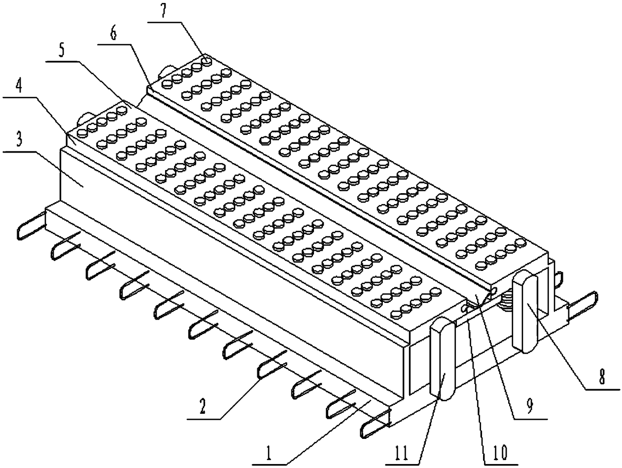
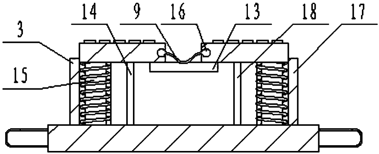
[0024] see Figure 1-3 , a telescopic device for an earthquake-resistant buffer bridge, comprising a main body base 1, anchors 2 are fixedly installed on both sides of the main body base 1, the anchors 2 are evenly distributed on both sides of the main body base 1, and the upper end of the main body base 1 is evenly fixed Shock-absorbing cylinder 15 is installed, and shock-absorbing cylinder 15 has eight, adopts two sides to arrange, and every side places four...


PUM


Abstract

The invention discloses a telescopic device of a shock-proof buffer type bridge. The telescopic device comprises a body base. Anchoring parts are installed on the two sides of the body base. Damping air cylinders are evenly arranged at the upper end of the body base. A first upper-layer supporting plate is installed at the upper end of the damping air cylinder on one side, a second upper-layer supporting plate is installed at the upper end of the damping air cylinder on the other side, longitudinal rigid displacement parts are installed on the two sides of the lower ends of the first upper-layer supporting plate and the second upper-layer supporting plate, and longitudinal elastic displacement parts are installed on the two sides of the lower ends of the first upper-layer supporting plate and the second upper-layer supporting plate. The damping effect is good, longitudinal and transverse displacement of the device can be subjected to rigid and elastic adjustment, the displacement adjusting amplitude is effectively increased while the rigidity of the device is guaranteed, damping of the device can be achieved, damage caused by impact to the device is avoided, partially independent displacement adjustment can be carried out, and the displacement adjusting effect is good.

Description

technical field [0001] The invention relates to the technical field of bridge auxiliary equipment, in particular to a telescopic device for an earthquake-resistant buffer bridge. Background technique [0002] Bridge expansion device refers to the expansion joints usually set between two girder ends, between the girder end and abutment or at the hinged position of the bridge in order to meet the deformation requirements of the bridge deck. It is required that the expansion joints can freely expand and contract in two directions parallel to and perpendicular to the bridge axis, and are firm and reliable. The vehicles should run smoothly without sudden jumps and noises; they should be able to prevent rainwater and garbage from infiltrating and blocking; installation, inspection, and maintenance , Elimination of dirt should be simple and convenient. The function of the bridge expansion device is to adjust the displacement and connection between the superstructure caused by the ...

Claims


Application Information

Patent Timeline
Patent Type & Authority Patents(China)
IPC IPC(8): E01D19/06
CPCE01D19/06
Inventor 陈余
Owner 徐州霞光机械制造有限公司
Learn More