Electrical tilt antenna monitoring system and method

An electronically adjustable antenna and monitoring system technology, which is applied in the transmission system, telephone communication, electrical components, etc., can solve the problem that there is no antenna information module commissioning function, telecom operators have not promoted and used it on a large scale, and the hand-held controller has a single function and other issues, to achieve the effect of easy network management analysis, important market value, and easy promotion

Inactive Publication Date: 2017-09-29
WUHAN HONGXIN TECH DEV CO LTD
View PDF5 Cites 5 Cited by
  • Summary
  • Abstract
  • Description
  • Claims
  • Application Information

AI Technical Summary

Problems solved by technology

[0002] With the rapid development of mobile communication technology, smart electronically adjustable antennas have been widely used in the field of communication. Intelligent electronically adjustable antennas are generally equipped with antenna information modules and electronically adjustable antenna controllers, antenna information modules and electronically adjustable antenna controllers Faults also increase proportionally with large-scale applications. It is a more effective and convenient method to use a hand-held controller to deal with the fault of an electronically adjustable antenna controller on site. However, the current hand-held controller has a single function and does not have antenna information module adjustment test function, and requires a backup battery, which is heavy and costly, and has not been widely used by telecom operators
If the antenna information module commissioning function is provided on the handheld controller, the cost will increase, far exceeding the handheld controller, so it is difficult to achieve

Method used


Image

  • Electrical tilt antenna monitoring system and method
  • Electrical tilt antenna monitoring system and method

Examples


Embodiment Construction

[0034] In order to better understand the present invention, the embodiments of the technical solutions of the present invention will be described in detail below with reference to specific embodiments and accompanying drawings.

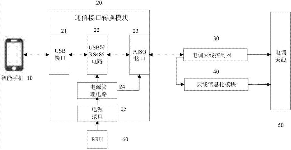
[0035] figure 1 It is a schematic structural diagram of an ESC antenna monitoring system based on a smart phone provided by an embodiment of the present invention. like figure 1 As shown, it includes a smart phone 10, a communication interface conversion module 20, an ESC antenna controller 30, an antenna informatization module 40, an ESC antenna 50, and an RRU 60;

[0036] The communication interface conversion module 20 includes a USB interface 21, a USB to RS485 circuit 22, an AISG interface 23, a power management circuit 24, and a power interface 25;

[0037] Wherein, the smart phone 10 is an Android phone with an OTG (On-The-Go) function, which is used for inputting user's instructions and data and displaying the instruction processing result. ...


PUM


Abstract

The invention provides an electrical tilt antenna monitoring system and method. The system comprises a smart phone and a communication interface conversion module. The communication interface conversion module comprises a USB interface, a USB to RS485 circuit and an AISG interface. The smart phone is connected with the USB interface. The USB interface is connected with a USB end of the USB to RS485 circuit. The AISG interface is connected with an RS485 end of the USB to RS485 circuit. The AISG interface is connected with an antenna information module and an electrical tilt antenna controller through an AISG cable. A user instruction is sent to the USB interface through the smart phone. The USB to RS485 circuit converts the user instruction from USB data into RS485 data and sends the RS485 data to the antenna information module and the electrical tilt antenna controller through the AISG interface. Operation response data is correspondingly returned to the smart phone. The system and the method are low in cost and are easy to popularize. Maintenance work can be conveniently carried out on a tower through utilization of a mobile phone and the communication interface conversion module, in large-scale radio communication operation, the economical benefits are remarkable, and the system and the method have important market value.

Description

technical field [0001] The present invention relates to the technical field of monitoring of electrically adjustable antennas, and in particular to an electrically adjustable antenna control system and method. Background technique [0002] With the rapid development of mobile communication technology, smart ESC antennas have been widely used in the field of communications. Smart ESC antennas are generally equipped with antenna information modules and ESC antenna controllers, antenna information modules and ESC antenna controllers. The fault also increases proportionally with the large-scale application. It is a more effective and convenient method to use the handheld controller to deal with the fault of the ESC antenna controller on site. However, the current handheld controller has a single function and does not have the antenna information module adjustment. It also requires a backup battery, which is cumbersome and expensive, and has not been widely used by telecom operat...

Claims


Application Information

Patent Timeline
Patent Type & Authority Applications(China)
IPC IPC(8): H04M1/725H04L29/06
CPCH04L69/08H04M1/72406H04M1/72409H04M1/72415
Inventor 王峥陈可陈羿伊刘海洲
Owner WUHAN HONGXIN TECH DEV CO LTD
Why Eureka
Try Eureka