Transmission layout

A transmission and planetary gear technology, which is applied in the field of transmission arrangement, can solve the problem that the transmission arrangement cannot be used, and achieve the effect of favorable transmission

Inactive Publication Date: 2019-10-15
RENK
View PDF9 Cites 0 Cited by
  • Summary
  • Abstract
  • Description
  • Claims
  • Application Information

AI Technical Summary

Problems solved by technology

In particular, the transmission arrangement known from DE 10 2012 013 834 A1 c

Method used


Image

  • Transmission layout
  • Transmission layout
  • Transmission layout

Examples


Example Embodiment

[0016] The invention relates to transmission arrangements.
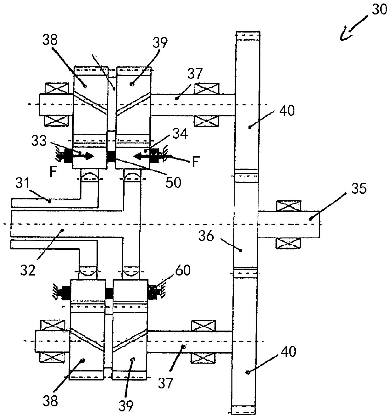
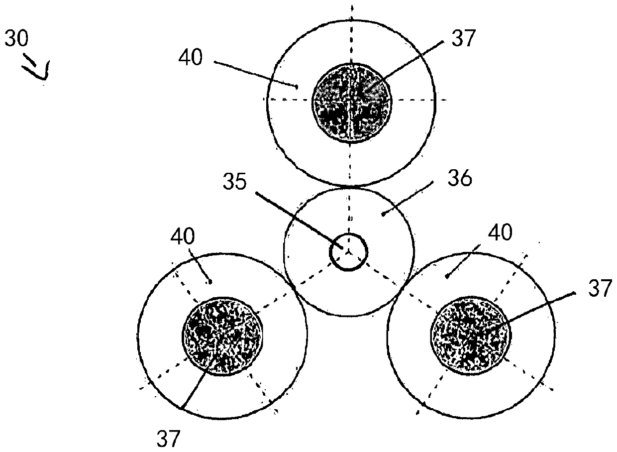
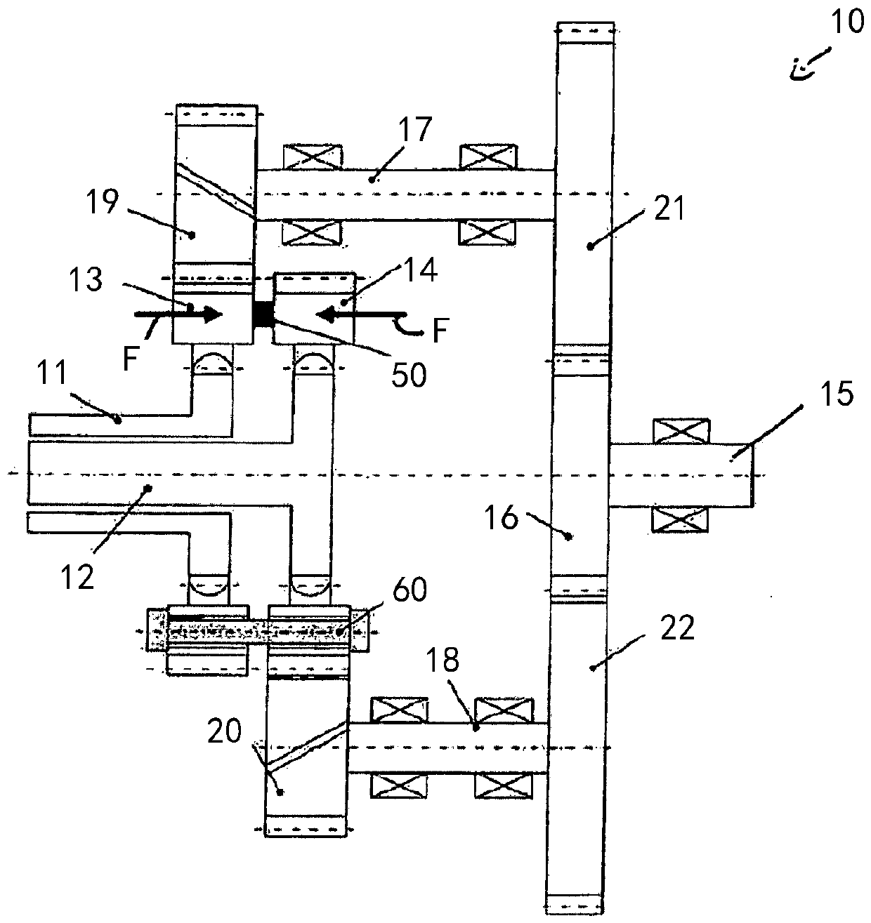
[0017] figure 1 with figure 2 The details of a preferred exemplary embodiment of the transmission arrangement 10 of the first aspect of the invention presented here are shown.

[0018] The transmission arrangement 10 includes two rotatably mounted drive side shafts, that is, a rotatably mounted first drive side shaft 11 and a rotatably mounted second drive side shaft 12. The two transmission side shafts 11, 12 extend coaxially with each other, wherein, in the exemplary embodiment shown, the first transmission side shaft 11 partially surrounds the second transmission side shaft 12 on the radially outer side. The first transmission tooth connection 13 is formed on the first transmission side shaft 11, and in the exemplary embodiment shown, the first transmission tooth connection 13 is provided by a gear. The second transmission gear joint 14 is formed on the second transmission side shaft 12, and similarly, the second tra...


PUM


Abstract

A transmission arrangement with a first rotatably mounted drive-side shaft paired with a first drive toothing; a second rotatably mounted drive-side side shaft paired with a second drive toothing; a rotatably mounted ouput-side shaft paired with an output toothing; a first number of first planet shafts, each of the first planet shafts being paired with a first planet toothing and a third planet toothing; and a second number of second planet shafts, each being paired with a second planet toothing and a fourth planet toothing. The first drive-side shaft and the second drive-side shaft are coaxially relative to each other; the first planet toothing engaged with the first drive toothing; the second planet toothing engaged with the second drive toothing; and the third planet toothing and the fourth planet toothing are engaged with the output toothing.

Description

technical field [0001] The invention relates to transmission arrangements. Background technique [0002] A transmission arrangement is known from DE 10 2012 013 83 A1, by means of which transmission power provided on a single transmission-side shaft can be transmitted in the direction of a single output-side shaft. In particular, the transmission arrangement known from DE 10 2012 013 834 A1 cannot be used when the transmission power is provided on both transmission side shafts. There is a need for a transmission arrangement which can transmit the transmission power from the two drive-side shafts in the direction of the output-side shaft. Contents of the invention [0003] Proceeding from this, the invention is based on the object of creating a new type of transmission arrangement. [0004] According to a first aspect of the invention, this object is solved by a transmission arrangement as described below. Accordingly, the transmission arrangement comprises: a rotatably ...

Claims


Application Information

Patent Timeline
IPC IPC(8): F16H3/44
CPCF16H3/44F16H2003/442F16H1/18F16H1/22F16H1/2836F16H1/46
Inventor B.平内坎普M.斯费尔
Owner RENK
Why Eureka
Try Eureka