Connector used for drawer connection slide rail

A connector and slide rail technology, which is applied in the field of connectors for drawer connecting slide rails, can solve the problems of insufficient precision, consistency, and disadvantageous comprehensive sliding performance of drawers and slide rails, and achieve the effect of improving sliding performance.

Active Publication Date: 2017-10-03
DONGGUAN GERUISI PRECISION HARDWARE TECH CO LTD
View PDF5 Cites 9 Cited by
  • Summary
  • Abstract
  • Description
  • Claims
  • Application Information

AI Technical Summary

Problems solved by technology

[0003] Those skilled in the art have analyzed the deficiencies of the existing known technologies. At present, due to installation and processing errors, it is difficult to ensure that the left and right heights are consistent when installing the left and right slide rails, causing the drawer to tilt left and right. If multiple drawers are installed up and down. It is more difficult to ensure a straight line, and even se

Method used


Image

  • Connector used for drawer connection slide rail
  • Connector used for drawer connection slide rail
  • Connector used for drawer connection slide rail

Examples


Embodiment 1

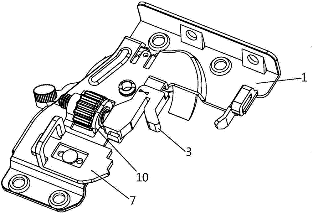
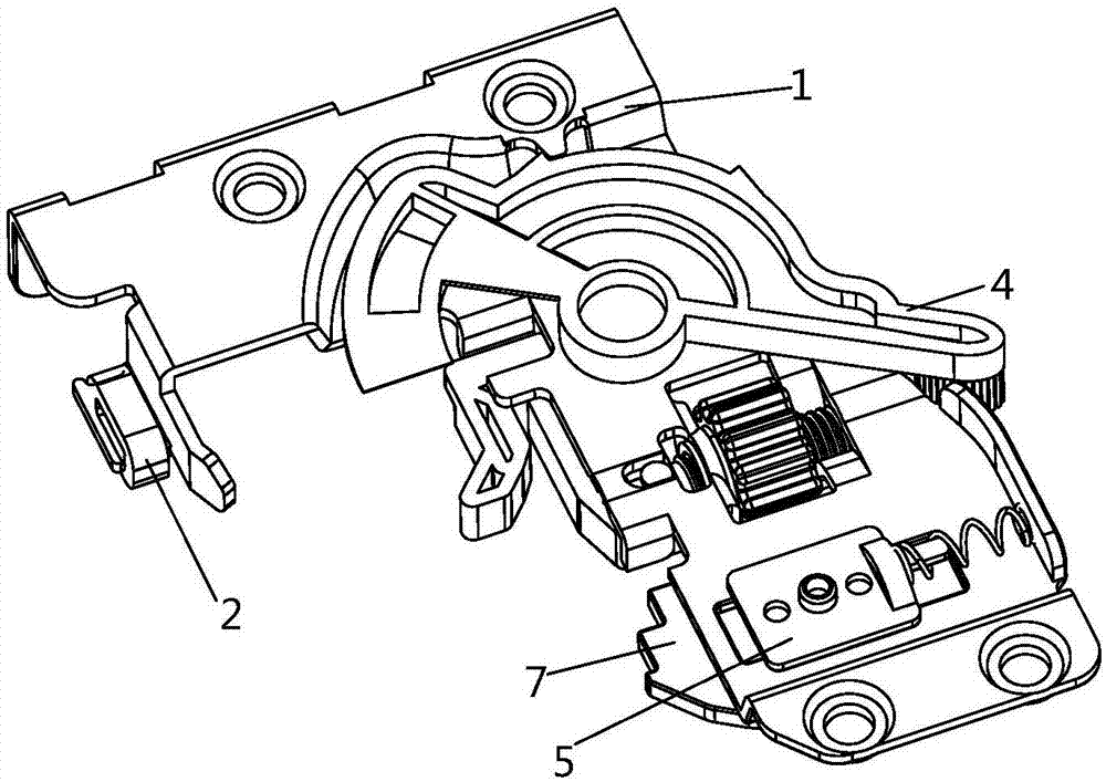
[0054] Such as figure 1 , Picture 1-1 , Figure 1-2 , figure 2 , diagram 2-1 , Figure 2-2As shown, the connector for connecting the drawer to the slide rail according to the embodiment of the present invention is composed of a bracket 1, a left and right adjustment arm 3, an up and down adjustment member 4, a positioning member 5, a telescopic member 7 and a positioning mechanism 10, The side edge of the bracket 1 has a rubber ring 2;

[0055] One of the characteristics of the technical solution implemented by the present invention is to cooperate with the above-mentioned telescopic member 7 and the bracket 1, and its technical characteristics are as follows:

[0056] One side of the telescopic member 7 has an upwardly protruding finger position 702, and the side where the finger position 702 is set is the front reference surface. The front reference surface of the telescopic member 7 has a rectangular depression and because the direction of the rectangular depression...

Embodiment 2

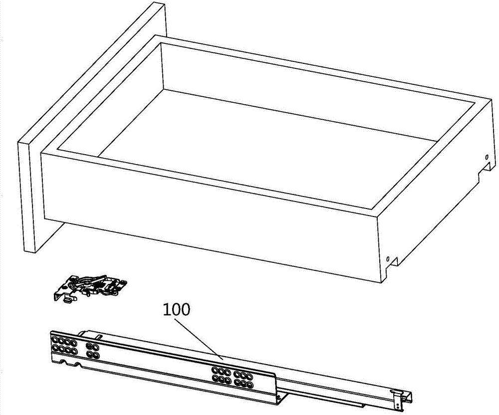
[0075] Such as figure 1 , Picture 1-1 , Figure 1-2 , figure 2 As shown, a slide rail device with a connector, the slide rail device is based on the connector for the drawer connecting slide rail in the first embodiment above, so that this embodiment is also the connection for the drawer connecting slide rail The application of the device, the slide rail device includes a connector and a track;

[0076] The connector includes a telescopic element 7:

[0077] A rectangular boss 701 is formed on the back of the telescopic member 7, and the rectangular boss 701 is embedded in the rectangular groove 101 of the bracket 1, thereby limiting the shaking of the left and right long sides of the telescopic member 7;

[0078] The connector also includes a positioning member 5:

[0079] The positioning column 50 of the positioning element 5 and the positioning hole 703 of the telescopic element 7 are riveted into one piece, and the shaking and displacement of the telescopic element ...

Embodiment 3

[0086] Such as figure 1 , Picture 1-1 , Figure 1-2 , figure 2 As shown, a method for realizing the sliding of the drawer slide rail consists of the following steps:

[0087] (1) A connector is installed between the slide rail and the drawer. The telescopic part 7 of the connector is provided with a rectangular boss 701 and the rectangular boss 701 is embedded in the rectangular groove 101 of the connector bracket 1;

[0088] (2) The connector also has a positioning piece 5, the positioning column 501 of the positioning piece 5 and the positioning hole 703 of the telescopic piece 7 are riveted into one piece to limit the shaking and displacement of the telescopic piece 7 above and below the rectangular groove 101; A spring 6 is arranged between the bracket 1 and the positioning member 5;

[0089] (3) The connector also includes an up and down adjustment member 4, a left and right adjustment arm 3, and a limit block 402 is respectively provided at both ends of the contact...


PUM


Abstract

The invention relates to a connector used for a drawer connection slide rail. The connector is composed of a support, a left-right regulating arm, an upper-lower regulating part, a positioning part, an extensible member and a positioning mechanism. The extensible member comprises a rectangular boss, the rectangular boss in embedded into a rectangular groove of the support in order to position the extensible member between the left and right long edges of the rectangular groove; the positioning part comprises at least two positioning columns, and the positioning columns and positioning holes of the extensible member are riveted and pressed to form a whole piece in order to position the extensible member in the rectangular groove in the vertical direction; a spring is arranged between the positioning part and the support, and the extensible member is maintained at one side of the rectangular groove under the action of the elastic force of the spring; stoppers are arranged on two ends of the part, of the upper-lower regulating part, which makes contact with the support, and the scope between the two stoppers forms a rotation scope for limiting the upper-lower regulating part. According to the invention, the connector can be matched with the slide rail accurately, the stability of each phase of the pushing process is achieved, and the sliding performance is improved.

Description

technical field [0001] The invention relates to a slide rail technology of a drawer, in particular to a connector for a drawer connecting a slide rail which is convenient for simultaneously satisfying the drawer installation, left and right height adjustment and left and right movement adjustment. Background technique [0002] The slide rail is a hardware connection part for the drawer or cabinet board of the furniture to move in and out. Many slide rail structures are suitable for the drawer connection of wooden and steel drawers such as cabinets, furniture, office cabinets, and bathroom cabinets. [0003] Those skilled in the art have analyzed the deficiencies of the existing known technologies. At present, due to installation and processing errors, it is difficult to ensure that the left and right heights are consistent when installing the left and right slide rails, causing the drawer to tilt left and right. If multiple drawers are installed up and down. It is even more ...

Claims


Application Information

Patent Timeline
IPC IPC(8): A47B88/423
Inventor 罗志明
Owner DONGGUAN GERUISI PRECISION HARDWARE TECH CO LTD
Why Eureka
Try Eureka