Concrete long distance linear distribution system and method

A cloth system, long-distance technology, applied in the direction of manufacturing tools, supply devices, etc., can solve the problems of insufficient cloth accuracy, small cloth radius, low output, etc., to achieve the effect of precise and continuous operation, and increase the linear distance.

Active Publication Date: 2022-07-05
广东康酷瑞装配式建筑有限公司
View PDF0 Cites 0 Cited by
  • Summary
  • Abstract
  • Description
  • Claims
  • Application Information

AI Technical Summary

Problems solved by technology

[0002] At present, the prefabricated construction industry is developing very rapidly, and various manufacturers have developed various types of concrete pouring equipment. However, the existing concrete pouring methods in engineering buildings are all centered on the distribution machine, using the rotation of the arm to move in the circumferential direction. It is impossible to achieve continuous and accurate pouring along the straight line. Although the pouring speed is very fast, it cannot be used for the production of concrete components. It is only suitable for engineering buildings. Concrete component factories use hoppers for pouring. But its pouring speed is slow and far behind the production capacity of the mixing system
This leads to large equipment investment and low output, causing many other production equipment to be idle, seriously affecting production efficiency and increasing labor costs
[0003] At the same time, at present, the production plants of prefabricated components of buildings mostly use concrete hoppers for pouring. Although the pouring efficiency has been improved through technological updates, continuous operation cannot be achieved.
Its pouring speed is still far behind the production capacity of the mixing system
If a fixed concrete placing machine is used, due to the limitation of the plant conditions, the distributing radius is small and the distributing accuracy is not enough, and a large amount of manpower is required to assist the concrete pouring operation
Moreover, the arrangement of component molds in building assembly factories is linear, which needs to form an assembly line operation, while the operating range of fixed distributing machines is circular, and its distributing efficiency cannot be effectively utilized
As a result, the pouring scheme using concrete delivery pumps combined with concrete distribution machines cannot be applied in the production of prefabricated factories

Method used


Image

  • Concrete long distance linear distribution system and method
  • Concrete long distance linear distribution system and method
  • Concrete long distance linear distribution system and method

Examples


Embodiment 1

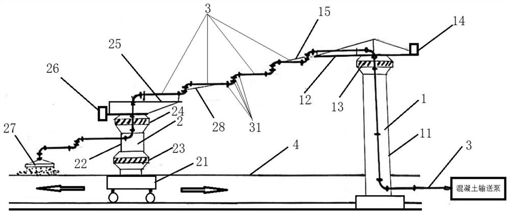
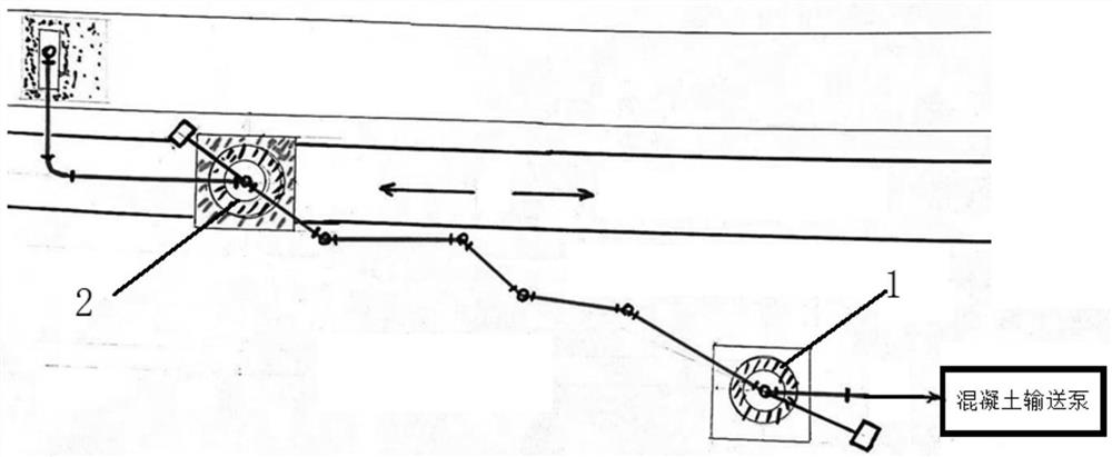
[0044] see Figure 1-2 , 5-6, according to a preferred embodiment of the present invention, there is provided a concrete long-distance linear distribution system, which includes:

[0045] The first distributing machine 1 is fixed on the site and includes a rotatable first arm 12 and a second arm 15;

[0046] The second distributing machine 2, which can reciprocate straightly along the first direction and includes a rotatable third arm 25 and a fourth arm 28; and

[0047]The concrete conveying pipe 3 includes a plurality of sub-conveying pipes hinged with each other through the joint 31, the first end of the concrete conveying pipe 3 ( figure 1 The right end in the middle) is connected to the concrete pump, and the second end ( figure 1 The left end in the middle) is connected to the pouring nozzle 27;

[0048] The concrete conveying pipe 3 extends from the first end to the bottom of the first distributor 1, the top of the first distributor 1, the first boom 12 and the secon...

Embodiment approach

[0056] According to another preferred embodiment of the present invention, a first turning mechanism 13 is provided on the upper part of the first distributing machine 1 . The second distributing machine 2 includes: a walking mechanism 21 arranged at the bottom; a column 22, which is arranged on the walking mechanism 21; a second rotating mechanism 24, which is arranged on the upper part of the column 22; and a third rotating mechanism 23, which is arranged on the The lower part of the upright column 22 ; the third arm rod 25 is disposed on the top of the upright column 22 ; and the fourth arm rod 28 is rotatably hinged to the second end of the third arm rod 25 . Preferably, the third arm rod 25 and the fourth arm rod 24 are arranged upside down.

[0057] It can be understood that the booms (the first and second booms) of the existing stationary spreader 1 are defined as normal settings, on the contrary, see figure 1 , the third arm 25 and the fourth arm 24 of the second dist...

Embodiment 2

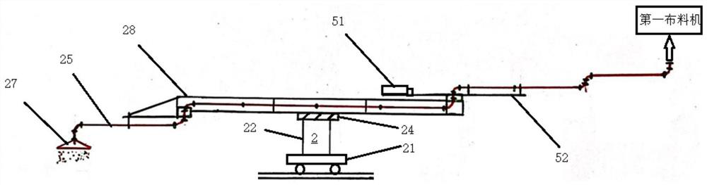
[0074] According to a preferred embodiment of the present invention, see figure 1 , provides a kind of walking type cloth machine 2, it is characterized in that including:

[0075] A walking machine arranged at the bottom, 21;

[0076] The upright column 22 is arranged on the walking mechanism 21;

[0077] Two swivel devices 23, 24 are respectively arranged on the upper and lower parts of the upright column 22;

[0078] The first arm rod 25 is arranged on the upright column 22 and has a first end and a second end, and the first end is provided with a counterweight 26;

[0079] The second arm rod 28 is rotatably hinged to the two ends of the first walking type distributing machine of the first arm rod 25; and

[0080]The concrete delivery pipe 3 has an inlet and an outlet, the inlet is located near the second end of the second arm 28 (the end away from the first arm 25 ) and at a first height, and the outlet is connected to the pouring nozzle 27 and at a second height, wher...


PUM


Abstract

A long-distance linear distribution system for concrete is provided, comprising: a first distribution machine, which is fixedly arranged on site and includes a rotatable first arm and a second arm; and includes a rotatable third arm rod and a fourth arm rod; and a concrete conveying pipe, including a plurality of sub conveying pipes hinged with each other through joints, the first end of the concrete conveying pipe is connected to the concrete conveying pump, and the second end is connected to the pouring nozzle; Wherein, the plurality of sub-conveying pipes between the uprights of the first distributing machine and the uprights of the second distributing machine can be changed between an extended state and a folded state with the reciprocating running of the second distributing machine. The distribution port can move in a straight line at a constant speed, and the pouring of the components can achieve precise and continuous operation at the same time.

Description

technical field [0001] The invention belongs to the field of prefabrication of concrete components, and in particular relates to a long-distance linear distribution system and method for concrete. Background technique [0002] At present, the prefabricated construction industry is developing very rapidly, and various manufacturers have developed various types of concrete pouring equipment. However, the existing concrete pouring methods in engineering buildings are all centered on the placing machine, using the rotation of the arm in the circumferential direction. It is not possible to achieve continuous and accurate pouring along the straight line. Although the pouring speed is fast, it cannot be used for the production of concrete components, and is only suitable for engineering construction. The concrete component factory uses hoppers for pouring, although the pouring is accurate However, its slow pouring speed is far behind the production capacity of the mixing system. T...

Claims


Application Information

Patent Timeline
Patent Type & Authority Patents(China)
IPC IPC(8): B28B13/02
CPCB28B13/021
Inventor 罗虎
Owner 广东康酷瑞装配式建筑有限公司
Why Eureka
Try Eureka