Conveying system

A technology of conveying system and conveying device, which is applied in the field of conveying system, and can solve the problems such as the deviation of the cloth from the transfer position and the difficulty of detaching from the electrified device

Active Publication Date: 2017-10-03
BROTHER KOGYO KK
View PDF6 Cites 4 Cited by
  • Summary
  • Abstract
  • Description
  • Claims
  • Application Information

AI Technical Summary

Problems solved by technology

Therefore, there is a possibility that because the cloth is in a charged state, it is difficult for a part of the cloth to escape from the charging device, thereby causing the cloth to deviate from the transfer position.

Method used


Image

  • Conveying system
  • Conveying system
  • Conveying system

Examples


Embodiment Construction

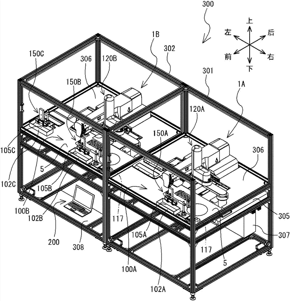
[0034] One embodiment of the present invention will be described with reference to the drawings. A schematic structure of the delivery system 300 will be described. The following description uses left and right, front and rear, and up and down indicated by arrows in the drawings.

[0035] Such as figure 1 As shown, the conveyance system 300 has two sewing machines, a sewing machine 1A and a sewing machine 1B, two conveyance devices, a conveyance device 100A and a conveyance device 100B, and one computer 200 . The sewing machine 1A and the sewing machine 1B have substantially the same configuration. In the following description, the sewing machine 1A and the sewing machine 1B are collectively referred to as the sewing machine 1 . The transport device 100A and the transport device 100B have substantially the same configuration. In the following description, the delivery device 100A and the delivery device 100B are collectively referred to as the delivery device 100 .

[003...


PUM


Abstract

The invention relates to a conveying system which can accurately and reliably configure a fabric material which is conveyed by a conveying apparatus to a delivery position which can be accepted by a sewing machine. The CPU of the conveying apparatus controls a moving mechanism, such that an absorption mechanism moves towards a configuration position. The CPU drives a charged apparatus and absorbs the fabric material which is disposed at the configuration position to the charged apparatus and moves the charged apparatus to the delivery apparatus. The CPU drives an absorption valve, and uses an absorption mechanism which is disposed at the delivery position to absorb the fabric material. The CPU stops to drive the charged apparatus, such that the charged apparatus releases the fabric material. The absorption mechanism positions the fabric material to the delivery position. The CPU stops to drive the absorption valve after the sewing machine uses a pressing plate to press the fabric material. The sewing machine can reliably receive the fabric material which is accurately positioned from the conveying apparatus.

Description

technical field [0001] The invention relates to a delivery system. Background technique [0002] There is a sewing machine for receiving cloth conveyed by a conveying device and sewing the cloth. The sewing machine receives the cloth conveyed to the transfer position by the conveying device, and holds the cloth by the holding body. The sewing machine moves the holder in the horizontal direction relative to the needle bar to sew the cloth. The static electricity generating member described in Japanese Patent Laid-Open No. 32125 of 2001 can fix the cloth to the charging device by generating static electricity, so that the cloth can be fixed when the cloth is conveyed by the conveying device. The cloth adsorbed to the charging device under the action of static electricity is not easy to be misaligned when being transported. Therefore, the conveying device can accurately convey the cloth to the delivery position. [0003] When transferring the cloth to the sewing machine, th...

Claims


Application Information

Patent Timeline
Patent Type & Authority Applications(China)
IPC IPC(8): D05B33/00D05B25/00D05B19/16
CPCD05B19/16D05B25/00D05B33/00D05D2207/04
Inventor 原田幸一田川祐二山浦宏贵
Owner BROTHER KOGYO KK
Why Eureka
Try Eureka