Deputy lock device comprising rotating shaft

A technology of rotating shaft and auxiliary lock, applied in the direction of building lock, building, building structure, etc., can solve the problems of inconvenience and many steps of closing the door, and achieve the effect of low manufacturing cost, compact structure, and quick opening or closing.

Active Publication Date: 2017-10-03
江西技德科技有限公司
View PDF27 Cites 2 Cited by
  • Summary
  • Abstract
  • Description
  • Claims
  • Application Information

AI Technical Summary

Problems solved by technology

[0004] In order to overcome the drawbacks of the prior art for opening and closing the doors of the side-by-side doors with many steps and inconvenient operations, the present invention provides a pair of rotating shafts on the auxiliary lock door. Locking device, in order to achieve the purpose of easy and fast operation when opening and closing the door

Method used


Image

  • Deputy lock device comprising rotating shaft
  • Deputy lock device comprising rotating shaft
  • Deputy lock device comprising rotating shaft

Examples


Embodiment 1

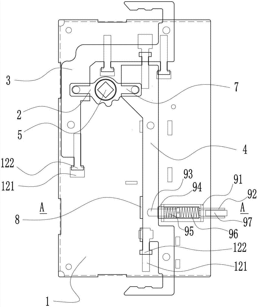
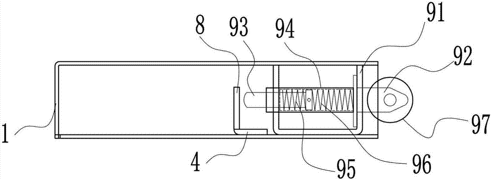
[0040] A rotary shaft auxiliary lock device, such as Figure 1 to Figure 4 As shown, it includes a lock case 1, a telescopic assembly that moves relative to the lock case 1, and a safety assembly installed on the lock case 1;

[0041] The telescopic assembly includes a swing rod 2, a transmission piece I3, and a transmission piece II4; the swing rod 2 is provided with a shaft hole 5, and two ends are provided with bumps 6; one end of the swing rod 2 is connected to the transmission piece I3 through the bump 6, and the other end is connected to the transmission piece I3. It is connected with the transmission piece II4; the transmission piece I3 and the transmission piece II4 are provided with groove I7, and the convex point 6 and the groove I7 are slidingly fitted; the transmission piece II4 is provided with a safety catch I8, such as Figure 15 shown;

[0042] The lock housing 1 is provided with a card slot 121, and both the transmission piece I3 and the transmission piece II...

Embodiment 2

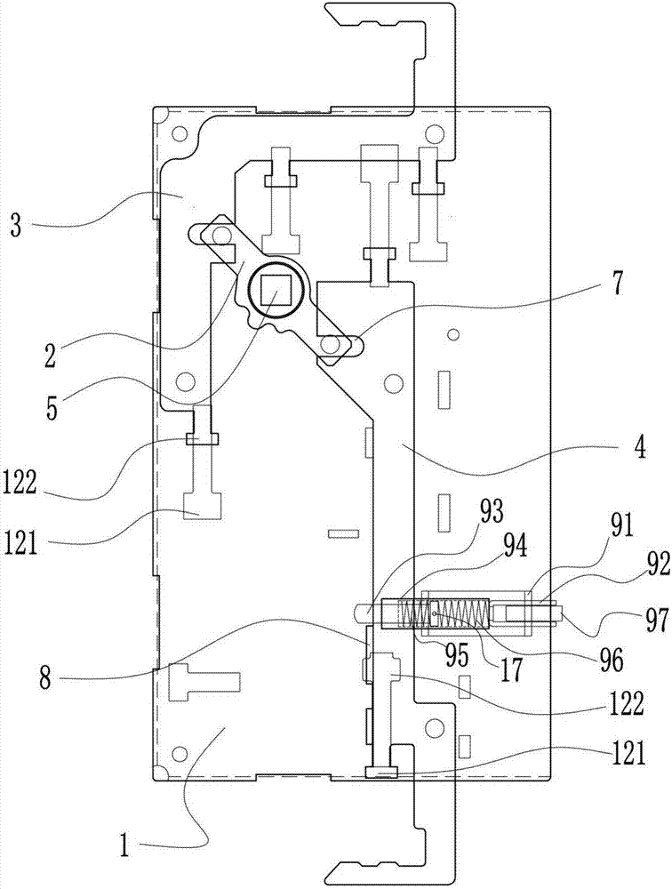
[0047] A rotary shaft auxiliary lock device, such as Figure 6 As shown, it includes a lock case 1, a telescopic assembly that moves relative to the lock case 1, and a safety assembly installed on the lock case 1;

[0048] The telescopic assembly includes a swing rod 2, a transmission piece I3, and a transmission piece II4; the swing rod 2 is provided with a shaft hole 5, and two ends are provided with bumps 6; one end of the swing rod 2 is connected to the transmission piece I3 through the bump 6, and the other end is connected to the transmission piece I3. It is connected with the transmission piece Ⅱ4; the transmission piece Ⅰ3 and the transmission piece Ⅱ4 are provided with the groove Ⅰ7, and the convex point 6 and the groove Ⅰ7 are slidably fitted; the transmission piece Ⅱ4 is provided with the safety catch Ⅰ8;

[0049] The drive piece I3 and the drive piece II4 are both provided with groove II131; the lock housing 1 is provided with a column point 132, and the column poi...

Embodiment 3

[0053] A rotary shaft auxiliary lock device, such as Figure 7 As shown, it includes a lock case 1, a telescopic assembly that moves relative to the lock case 1, and a safety assembly installed on the lock case 1;

[0054] The telescopic assembly includes a swing rod 2, a transmission piece I3, and a transmission piece II4; the swing rod 2 is provided with a shaft hole 5, and two ends are provided with bumps 6; one end of the swing rod 2 is connected to the transmission piece I3 through the bump 6, and the other end is connected to the transmission piece I3. It is connected with the transmission piece Ⅱ4; the transmission piece Ⅰ3 and the transmission piece Ⅱ4 are provided with the groove Ⅰ7, and the convex point 6 and the groove Ⅰ7 are slidably fitted; the transmission piece Ⅱ4 is provided with the safety catch Ⅰ8;

[0055] The lock housing 1 is provided with a chute 14 , and the transmission piece I3 and the transmission piece II4 pass through the chute 14 and move in the ch...


PUM


Abstract

The invention belongs to the field of manufacturing of household doors and windows, particularly relates to a deputy lock device comprising a rotating shaft, and provides the deputy lock device comprising the rotating shaft so as to overcome the defects that double-doors in the prior art are opened and closed inconveniently through multiple steps. The device comprises a lock casing, a telescopic assembly moving relative to the lock casing and a security assembly mounted on the lock casing; the telescopic assembly comprises a swing rod, a transmission piece I and a transmission piece II; and the security assembly comprises a supporting frame, a transmission shaft and a sleeve. The device has the beneficial effects as follows: after a connecting rod device is externally connected onto the device, doors can be opened or closed inside or outside, so that the double doors are opened or closed conveniently and quickly.

Description

technical field [0001] The invention belongs to the field of door and window manufacturing, and in particular relates to a rotating shaft secondary lock device. Background technique [0002] At present, the common side-by-side doors on the market are composed of a door frame, two doors, a main lock, a sky lock, a ground lock, and a tongue hole installed in the door frame; the structure of the two doors is that the main lock is set on one door, Hereinafter referred to as the main lock door, the other door is provided with the main lock hole corresponding to the main lock, the sky lock installation hole, the ground lock installation hole, hereinafter referred to as the auxiliary lock door; the sky lock and the earth lock are respectively installed on the auxiliary lock door. 1. In the installation hole of the ground lock, the sky lock and the ground lock are bolt-type. It is necessary to manually control the bolts of the sky and ground locks up and down respectively to lock th...

Claims


Application Information

Patent Timeline
Patent Type & Authority Applications(China)
IPC IPC(8): E05B65/06E05B15/00
CPCE05B15/00E05B65/0003E05B65/06
Inventor 刘庭权
Owner 江西技德科技有限公司
Why Eureka
Try Eureka