
Compressor and air conditioner

A compressor and high-pressure gas technology, applied in the direction of machines/engines, mechanical equipment, liquid fuel engines, etc., can solve the problems of low energy efficiency, detachment, abnormal noise of compressors, etc., to prevent noise, avoid gas leakage, and prevent detachment Effect

Active Publication Date: 2017-10-03
GREE ELECTRIC APPLIANCES INC
View PDF7 Cites 5 Cited by
  • Summary
  • Abstract
  • Description
  • Claims
  • Application Information

AI Technical Summary

Problems solved by technology

Due to the small pressure difference between the head and the tail at low speed, relatively high speed is prone to the phenomenon that the sliding vanes and rollers of the compressor are separated, resulting in air leakage in the compression chamber and suction chamber of the compressor, resulting in low-frequency operation of the compressor The energy efficiency is very low, and the collision between the slide and the roller will produce abnormal noise

Method used


Image

  • Compressor and air conditioner
  • Compressor and air conditioner
  • Compressor and air conditioner

Examples


Embodiment Construction

[0036] In order to make the objectives, technical solutions and advantages of the present invention clearer, the technical solutions of the present invention will be described clearly and completely with reference to specific embodiments of the present invention and the corresponding drawings. Obviously, the described embodiments are only a part of the embodiments of the present invention, rather than all the embodiments. Based on the embodiments of the present invention, all other embodiments obtained by those of ordinary skill in the art without creative work shall fall within the protection scope of the present invention.

[0037] It should be noted that the terms "first" and "second" in the specification and claims of the present invention and the above-mentioned drawings are used to distinguish similar objects, and not necessarily used to describe a specific sequence or sequence. It should be understood that the data used in this way can be interchanged under appropriate cir...


PUM


Abstract

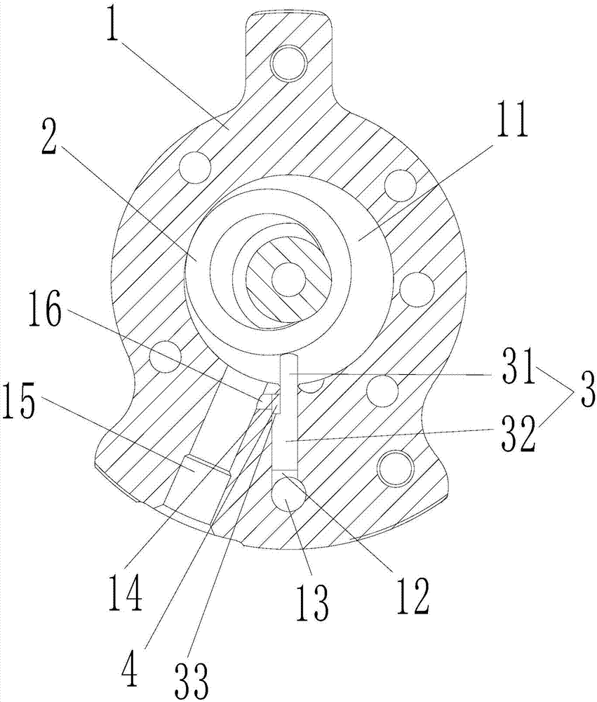
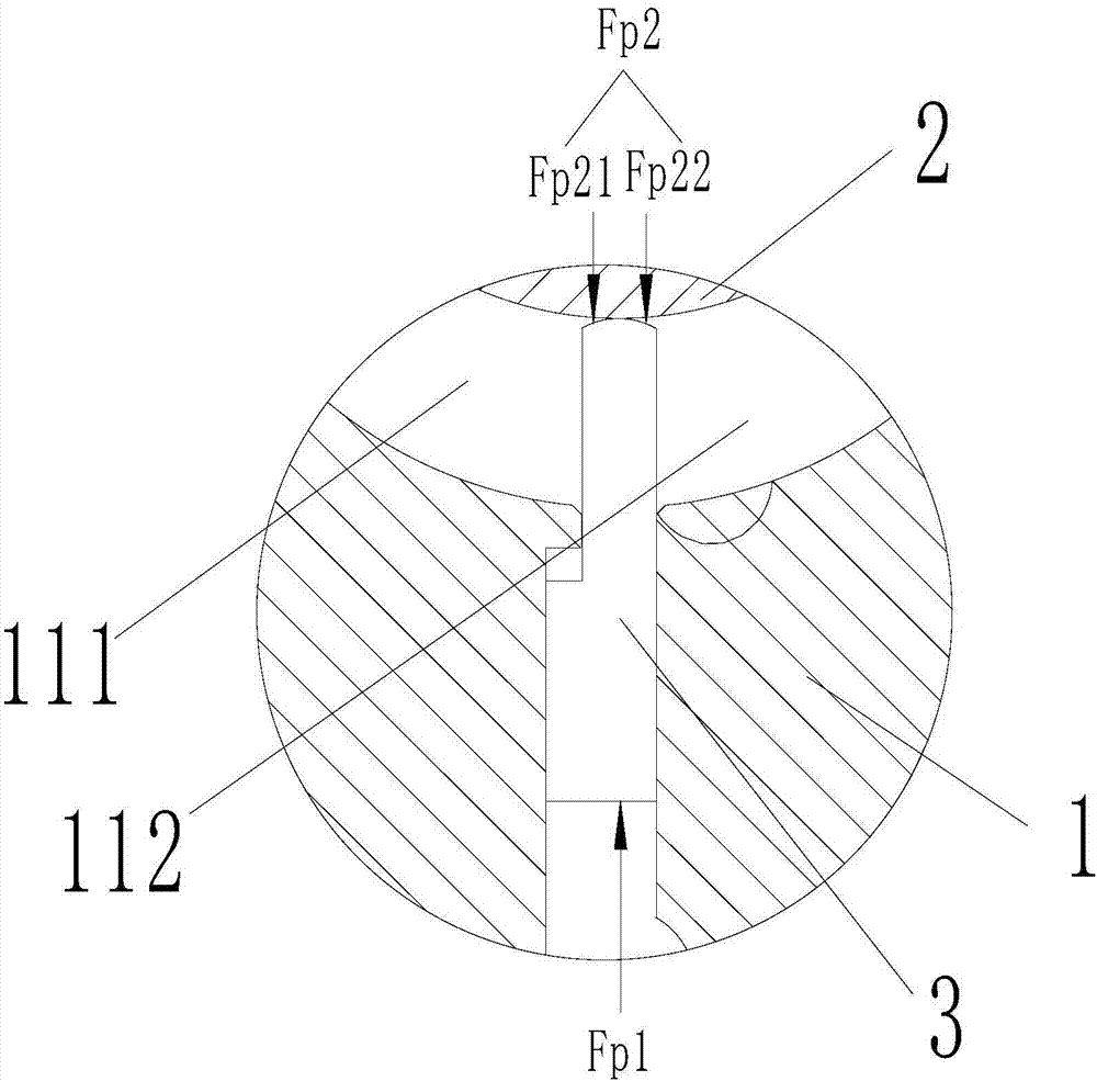
The invention provides a compressor and an air conditioner. The compressor comprises an air cylinder, a roller and a sliding vane; the air cylinder is provided with a sliding vane slot and a ventilating hole, the ventilating hole is formed outside the sliding vane slot, one end of the sliding vane slot communicates with an inner cavity of the air cylinder, and high-pressure gas in the compressor is introduced into the other end of the sliding vane slot through the ventilating hole; the roller is arranged in the inner cavity, and the sliding vane is at least partially arranged in the sliding vane slot and can move in the sliding vane slot; and the two ends of the sliding vane are provided with a first end face for abutting against the roller and a second end face for bearing the pressure of the high-pressure gas entering through the ventilating hole correspondingly, and the area of the second end face is larger than that of the first end face. The compressor and the air conditioner have the advantages that the sliding vane is prevented from being separated from the roller, blow-by between a compression cavity and a suction cavity can be avoided, and noise generated by impact between the sliding vane and the roller can also be prevented.

Description

Technical field [0001] The invention relates to the technical field of compressor manufacturing, in particular to a compressor and an air conditioner. Background technique [0002] The compressor is an important refrigeration component in the air conditioner. With the development of frequency conversion technology, the speed of the compressor is getting lower and lower. [0003] At present, the cylinder structure of the compressor is abutted on the roller through the sliding vane to separate the compression chamber of the cylinder into a suction cavity and a compression cavity. At the same time, the tail of the sliding vane bears the pressure generated by the air pressure outside the cylinder, and the head Withstand the pressure generated by the air pressure inside the cylinder, and rely on the pressure difference between the head and the tail to realize the contact between the sliding vane and the roller. Since the pressure difference between the head and the tail is small at low...

Claims


Application Information

Patent Timeline
Patent Type & Authority Applications(China)
IPC IPC(8): F04C18/344F04C29/06
CPCF04C18/344F04C29/06
Inventor 胡余生张荣婷张金圈商远杰
Owner GREE ELECTRIC APPLIANCES INC
Learn More