Electrolyte injection apparatus for battery

A liquid injection device and battery technology, applied in battery pack parts, circuits, electrical components, etc., can solve problems such as low battery injection efficiency, and achieve the effect of improving the injection rate

Inactive Publication Date: 2016-10-26
QINGHAI CONTEMPORARY AMPEREX TECH
View PDF5 Cites 6 Cited by
  • Summary
  • Abstract
  • Description
  • Claims
  • Application Information

AI Technical Summary

Problems solved by technology

However, according to the existing vacuum liquid injection method, the amount of electrolyte solution injected into the battery each time is small, so a large number of repeated operations are required to complete the sufficient liquid injection of the battery, resulting in low efficiency of battery liquid injection

Method used


Image

  • Electrolyte injection apparatus for battery

Examples


Embodiment Construction

[0045] The present application will be described in further detail below through specific embodiments and in conjunction with the accompanying drawings. "Front", "rear", "left", "right", "upper" and "lower" in the text all refer to the state of the liquid storage chamber in the drawings.

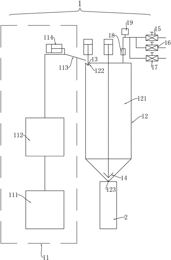
[0046] Such as figure 1 As shown, the battery liquid injection device of the embodiment of the present application includes: a liquid supply mechanism 11 , a liquid injection cup 12 , a liquid injection sealing valve 13 , a vacuum valve 15 and a positive pressure valve 16 .

[0047] The liquid injection cup 12 includes: a liquid storage chamber 121, a first liquid inlet 122, a second liquid outlet 123, a vacuum port and a positive pressure port; a first liquid inlet 122, a second liquid outlet 123, a vacuum port and a positive pressure The pressure ports are respectively connected with the liquid storage chamber 121; the first liquid inlet 122 is also connected with the liquid supply mechan...


PUM


Abstract

The invention provides an electrolyte injection apparatus for a battery, belonging to the field of batteries. The objective of the invention is to provide the electrolyte injection apparatus capable of improving the electrolyte injection rate of the battery. The electrolyte injection apparatus comprises an electrolyte supplying mechanism, an electrolyte injection cup, an injected electrolyte sealing valve, a vacuum valve and positive valve, wherein the electrolyte supplying mechanism comprises an electrolyte storage box and a first electrolyte outlet; the first electrolyte outlet is communicated with the electrolyte storage box; the electrolyte injection cup comprises an electrolyte storage chamber, a first electrolyte inlet, a second electrolyte outlet, a vacuum opening and a positive voltage opening; the first electrolyte inlet, the second electrolyte outlet, the vacuum opening and the positive voltage opening are separately communicated with the electrolyte storage chamber; when an electrolyte is stored in the electrolyte storage chamber, the electrolyte can flow into the second electrolyte outlet and not into the vacuum opening; the first electrolyte outlet may be communicated with the first electrolyte inlet; the second electrolyte outlet is used for hermetic butt joint with an electrolyte inlet of the battery; the injected electrolyte sealing valve is matched with the first electrolyte inlet and can seal and open the first electrolyte inlet; the vacuum valve is communicated with the vacuum opening; and the positive valve is communicated with the positive voltage opening.

Description

technical field [0001] The present application relates to the field of batteries, in particular to a battery liquid injection device. Background technique [0002] In the battery production process, electrolyte filling is a very important link. Vacuum liquid injection is one of the commonly used liquid injection methods. Generally, the vacuum liquid injection method first injects the electrolyte into the cache cup, then vacuumizes the cache cup and the battery to a certain value, then opens the cache cup, and vacuums the electrolyte. fluid is sucked into the battery. However, according to the existing vacuum liquid injection method, the amount of electrolyte solution injected into the battery each time is small, so a large number of repeated operations are required to complete the sufficient liquid injection of the battery, resulting in low efficiency of battery liquid injection. Contents of the invention [0003] The problem to be solved in this application is to provid...

Claims


Application Information

Patent Timeline
Patent Type & Authority Applications(China)
IPC IPC(8): H01M2/36
CPCH01M50/60Y02E60/10
Inventor 王蜀玖林细福
Owner QINGHAI CONTEMPORARY AMPEREX TECH
Why Eureka
Try Eureka