Mixed flow magnetorheological valve

A magneto-rheological valve, flow-type technology, applied to valve details, valve devices, engine components, etc., can solve the problems of increasing the magnetic induction intensity of the damping gap, failure of magnetorheological valves, and increased manufacturing costs, and achieves increased shear The effect of large area, large controllable range and fast response speed

Inactive Publication Date: 2015-04-08
EAST CHINA JIAOTONG UNIVERSITY
View PDF5 Cites 7 Cited by
  • Summary
  • Abstract
  • Description
  • Claims
  • Application Information

AI Technical Summary

Problems solved by technology

The commonly used method is to reduce the width of the damping gap of the magnetorheological valve, but when the magnetorheological fluid is left unused for a long time and restarted, particles are prone to precipitate and block the damping gap, resulting in the failure of the magnetorheological valve
The second is to increase the length of the damping gap, but this will significantly increase the volume of the magnetorheological valve, occupy more installation and use space, and increase the manufacturing cost accordingly
[0005] Based on this, in the actual design process, it is difficult to simultaneously increase the magnetic induction intensity in the damping gap and increase the length of the effective damping gap

Method used


Image

  • Mixed flow magnetorheological valve
  • Mixed flow magnetorheological valve
  • Mixed flow magnetorheological valve

Examples


Embodiment Construction

[0015] Below in conjunction with accompanying drawing and embodiment the present invention will be further described:

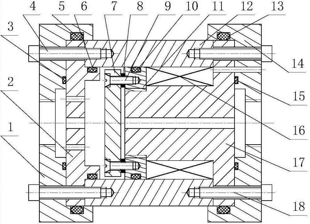
[0016] like figure 1 As shown, the present invention includes: left end cover (1), deflector plate (2), seal ring I (3), screw I (4), seal ring II (5), seal ring III (6), magnetic conduction circle Plate (7), washer (8), counterbore screw (9), seal ring IV (10), positioning plate (11), valve body (12), seal ring V (13), right end cover (14), seal Circle VI (15), coil (16), spool (17) and screw II (18).

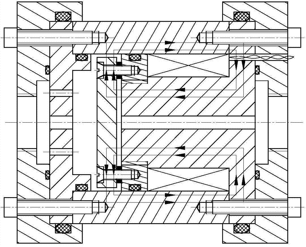
[0017] When assembling, first install the positioning disc (11) with the sealing ring IV (10), and then thread the valve core (17) to ensure the axial distance; then wind the coil (16) around the positioning disc (11) and the valve core (17) In the winding slot that forms, at last two wires of the coil that are wrapped are drawn out from the 2mm circular hole on the upper right end face of the spool (17). The magnetic conducting disk (7) is fixedly connect...


PUM


Abstract

The invention discloses a mixed flow magnetorheological valve which comprises a left end cover, a valve spool, a valve body, a guide disk, a magnetic disk, a positioning disk, a gasket, a coil, a sealing ring, a screw and a right end cover. A flow passage between the magnetic disk and the valve body forms an axial damping gap, and flow passages among the magnetic disk, the valve body and the valve spool form radial damping gaps. When current is inputted into the coil, magnetic lines vertically penetrate the axial and radial damping gaps, and the magnetic induction intensity is generated under the action of a magnetic field. The pressure difference in the axial and radial damping gaps can be controlled by adjusting the strength of the current. By the aid of the structure, the magnetorheological valve has enough pressure difference, clogging of the valve is avoided, the performance of the valve is more stable, the adjustable range of the pressure difference is wider, and the magnetorheological valve is accurate in damping gap positioning, compact in structure, small in size, convenient to assemble, particularly suitable for serving as a damper bypass valve and applied to damping systems of industries such as a railway and a traffic.

Description

technical field [0001] The invention relates to a magnetorheological valve, in particular to a mixed flow magnetorheological valve. Background technique [0002] In the hydraulic control system, the control valve is mainly used to control the pressure, flow and flow direction of the liquid flow in the actuator to meet the requirements of various hydraulic equipment for load conditions such as motion, speed, force and torque. Therefore, the performance of the hydraulic control valve directly affects the static, dynamic characteristics and working reliability of the hydraulic system, and it is the core control unit in the hydraulic control system. With the development of high technology, the engineering application of hydraulic transmission has higher and higher requirements for hydraulic components. Due to the existence of moving mechanical parts, traditional hydraulic control valves are not only complex in structure, large in size, high in processing requirements, easy to we...

Claims


Application Information

Patent Timeline
Patent Type & Authority Applications(China)
IPC IPC(8): F16K13/10F16K31/06
CPCF16K13/10F16K31/0675
Inventor 胡国良廖明科李卫华
Owner EAST CHINA JIAOTONG UNIVERSITY
Why Eureka
Try Eureka