Wind power generator blade, wind power generator cooling device and wind power generator unit

A technology for wind turbines and heat sinks, applied in the fields of wind turbines, wind turbine blades, and wind turbine heat sinks, can solve the problem of reducing the stability and reliability of wind turbines, increasing the cost and energy consumption of wind turbines, Affecting the heat dissipation effect of wind turbines and other issues, to achieve the effect of reducing weight, improving heat dissipation efficiency, and good reliability

Active Publication Date: 2016-08-17
BEIJING GOLDWIND SCI & CREATION WINDPOWER EQUIP CO LTD
View PDF8 Cites 7 Cited by
  • Summary
  • Abstract
  • Description
  • Claims
  • Application Information

AI Technical Summary

Problems solved by technology

[0007] 1. It is necessary to add a motor and a motor control device to drive the air circulation movement, which increases the cost and energy consumption of the wind turbine, and leads to an increase in the weight of the wind turbine;
[0008] 2. Whether it is heat dissipation by heat convection or heat conduction, the heat dissipation range is limited to the nacelle and its surroundings, and cannot effectively dissipate heat from other wind turbine equipment such as converters and main control switch cabinets;
[0009] 3. The cooling device has relatively high requirements on the reliability of the motor. Once the motor of the cooling device fails, it will seriously affect the heat dissipation effect of the wind turbine, which will cause the wind turbine to not work normally, thereby reducing the stability and stability of the wind turbine. reliability

Method used


Image

  • Wind power generator blade, wind power generator cooling device and wind power generator unit
  • Wind power generator blade, wind power generator cooling device and wind power generator unit
  • Wind power generator blade, wind power generator cooling device and wind power generator unit

Examples


Embodiment 1

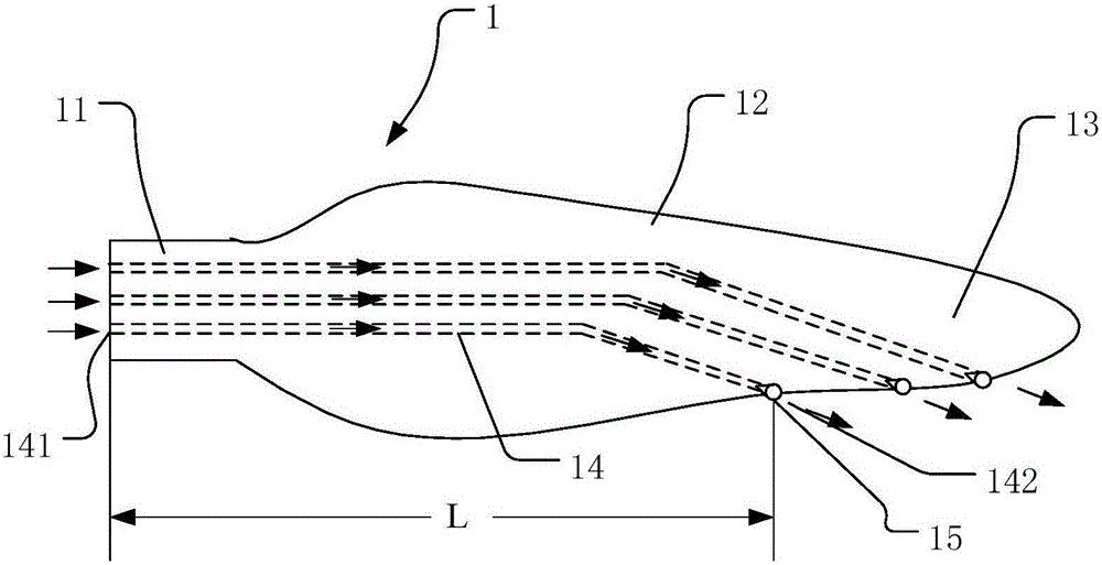
[0042] figure 1 It shows the wind power generator blade 1 according to Embodiment 1 of the present invention, including the blade root 11 and the blade main body 12; it also includes: the air inlet 141, which is arranged at the blade root 11; the air outlet 142, which is arranged at the blade The outer surface of the main body 12 ; the blade air channel 14 is arranged inside the wind turbine blade 1 and communicates with the air inlet 141 and the air outlet 142 ; the anti-backflow mechanism 15 is arranged at the air outlet 142 .

[0043]The wind power generator blade 1 provided in Embodiment 1, by setting the blade air channel 14 inside and the air outlet 142 on the outer surface, when the wind power generator blade 1 rotates with the hub 2, between the air inlet 141 and the air outlet 142 Forming an air pressure difference (the specific principle of forming an air pressure difference will be described in Embodiment 2 in conjunction with the cooling device of the wind power ge...

Embodiment 2

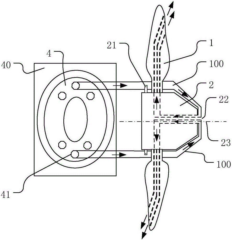
[0052] figure 2 and image 3 The structural diagram and principle diagram of the cooling device for wind power generators in the second embodiment are shown.

[0053] The heat dissipation device of the wind power generator in the second embodiment includes a cabin for accommodating heating elements, a hub 2 , the blade 1 of the wind power generator as described in the first embodiment, and a cooling channel. Wherein, the blade 1 is fixedly connected with the hub 2 ; the cooling channel connects the cabin and the air inlet 141 of the wind turbine blade 1 .

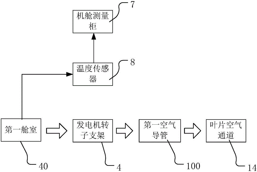
[0054] The cabin in this embodiment refers to the cabin that is arranged in the wind power generator and accommodates heating elements that generate heat during operation. For example, the cabin can be the inner cavity of the generator or a cabin for accommodating switch cabinets or current cabinets, etc., but it is not limited to the above cabins. Any cabin that needs heat dissipation in the wind generator is within the...

Embodiment 3

[0094] Figure 4 and Figure 5 It is a structural diagram and a schematic diagram of a heat dissipation device for a wind power generator according to Embodiment 3 of the present invention. The difference between the cooling device for wind-driven generators in Embodiment 3 and the embodiment of dissipating heat for the first compartment 40 in Embodiment 2 is that the cooling device for wind-driven generators in Embodiment 3 can be a second compartment 50 different from the first compartment 40 Heat dissipation. The second compartment 50 may be a compartment for accommodating a converter or a main control switchgear, but is not limited to the above-mentioned compartments, and may also be other compartments different from the first compartment 40 and requiring heat dissipation.

[0095] Specifically, the difference between the second compartment 50 and the first compartment 40 is that the first compartment 40 is the inner chamber of the generator, and the first compartment 40...


PUM


Abstract

The invention provides a wind power generator blade, a wind power generator cooling device and a wind power generator unit. The wind power generator blade comprises a blade root and a blade body, and further comprises air inlets, air outlets, blade air channels and backflow prevention devices, wherein the air inlets are formed in the blade root; the air outlets are formed in the outer surface of the blade body; the blade air channels are formed in the blade and enable the air inlets and the air outlets to communicate; and the backflow prevention devices are arranged at the air outlets. According to the wind power generator blade, the blade air channels are arranged in the blade, the air outlets are formed in the outer surface, and accordingly air at the air inlets can be guided to the air outlets through the blade air channels and then discharged. Through the pressure difference generated by the blade during rotating, moving airflow from a cabin to the air outlets of the blade is formed, and then heat in the cabin is dissipated.

Description

technical field [0001] The invention relates to the field of wind power generators, in particular to a wind power generator blade, a wind power generator cooling device and a wind power generator set. Background technique [0002] Generator heat dissipation is the main and important part of wind turbine heat dissipation. Its structure and efficiency determine the capacity, structure, and performance of wind turbine generators. At this stage, high-power (greater than 2MW) permanent magnet direct drive generators are often used for heat dissipation. Although the structure of the active air cooling method is different, the cost, equipment used, and space occupied are roughly the same, and the heat dissipation efficiency varies greatly according to the heat dissipation requirements. [0003] For example: in a heat dissipation device for a wind power generator, the heat dissipation process is to use the exhaust fan to make the hot air in the generator convectively exchange heat w...

Claims


Application Information

Patent Timeline
Patent Type & Authority Applications(China)
IPC IPC(8): F03D1/06F03D9/25F03D80/60
CPCF03D1/065F05B2260/20Y02E10/72
Inventor 葛俊豪王砼
Owner BEIJING GOLDWIND SCI & CREATION WINDPOWER EQUIP CO LTD
Why Eureka
Try Eureka