Display panel

A display panel and display area technology, applied to static indicators, static memory, instruments, etc., can solve problems such as manufacturing process errors, display function deterioration, gate control signal impedance mismatch, etc., to reduce the number of switches and improve tolerance range effect

Active Publication Date: 2014-12-10
AU OPTRONICS CORP
View PDF6 Cites 12 Cited by
  • Summary
  • Abstract
  • Description
  • Claims
  • Application Information

AI Technical Summary

Problems solved by technology

[0007] The purpose of the present invention is to provide a display panel to solve the problem that the existing driving circuit has poor uniformity of light emission of the display panel due to the impedance mismatch of the gate control signal during driving, and the existing driving circuit needs more time. Multi-transistor, easy to cause deterioration of display function due to manufacturing process errors

Method used


Image

  • Display panel
  • Display panel
  • Display panel

Examples


Embodiment Construction

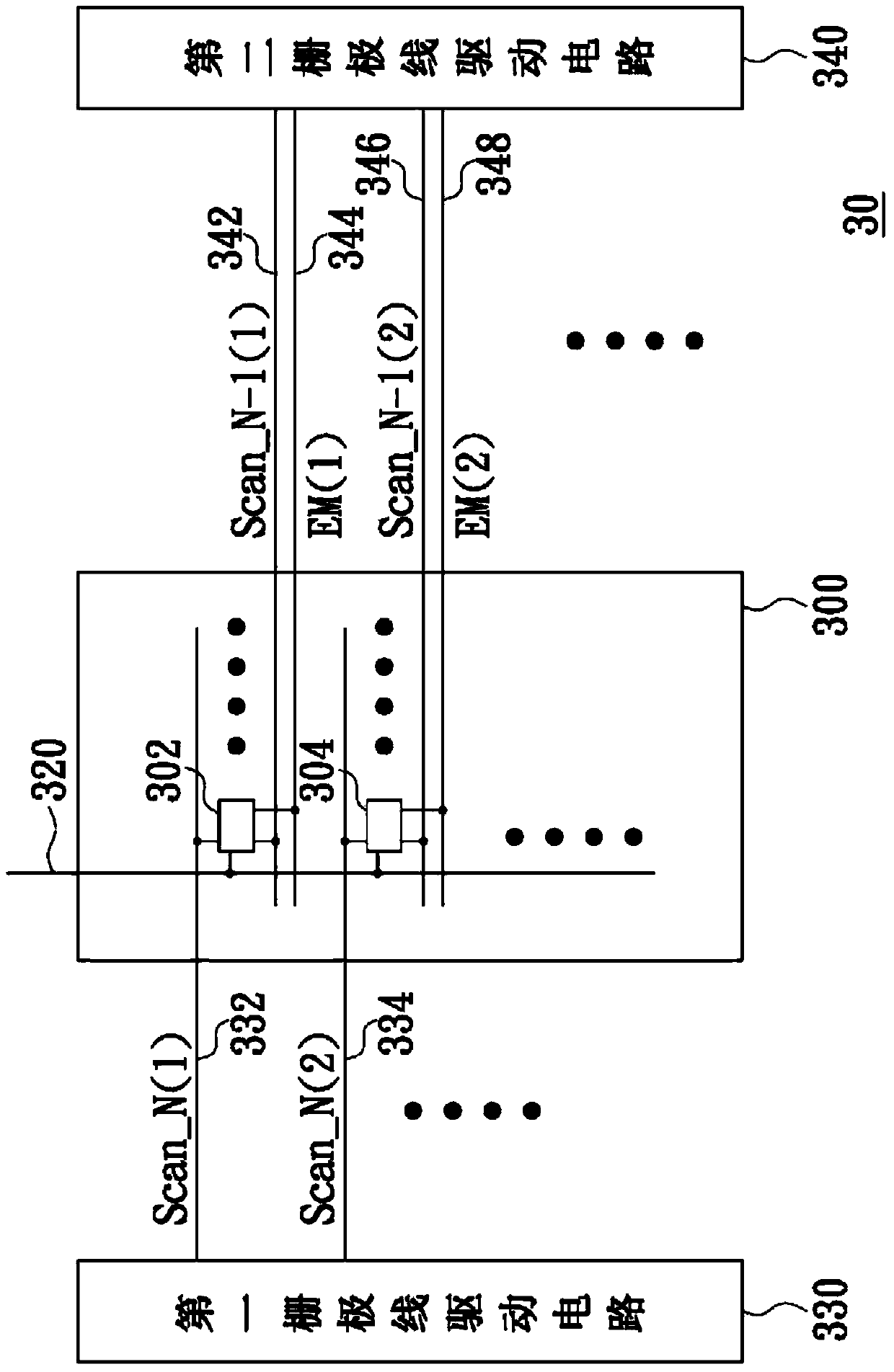
[0077] Please refer to image 3 , which is a circuit block diagram of a flat panel display according to an embodiment of the present invention. In this embodiment, the flat panel display 30 includes a display area 300, a first gate line driver circuit 330, a second gate line driver circuit 340, a data line 320, first gate lines 332 and 334, a second gate line 342 and 346 and lighting control lines 344 and 348 . In addition, there are a plurality of pixels 302 and 304 in the display area 300 , and each pixel is affected by the corresponding first and second gate lines and light emission control lines. For example, the pixel 302 is electrically coupled to the first gate line 332 , the second gate line 342 , the light emission control line 344 and the data line 320 , and according to the first control signal Scan_N transmitted by the first gate line 332 (1) (hereinafter referred to as Scan_N generally referred to as the gate control signal) and the second control signal Scan_N-...


PUM


Abstract

The invention provides a display panel. The display panel comprises a first gate line driving circuit and a second gate line driving circuit, which are respectively arranged on two sides of a display area, and controls the same pixel in the display area via a first gate line and a second gate line. The first gate line driving circuit is electrically coupled to the first gate line so as to provide a first control signal to the first gate line. The second gate line driving circuit is electrically coupled to the second gate line so as to provide a second control signal to the second gate line. In addition, the second gate line driving circuit is electrically coupled to a luminance control line so as to provide a luminance control signal to the luminance control line and control the same pixel to emit light at any time via the luminance control line. According to the invention, a gate control signal generator is divided into two areas, so uniformity of luminance of the display panel is better, and poor display effects caused by influences on normal operation of circuits due to errors in manufacturing technique are avoided.

Description

technical field [0001] The present invention relates to a display panel, in particular to a driving circuit of the display panel. Background technique [0002] A flat-panel display is a display device that displays images based on pixel circuits, and different pixel circuits may require different driver circuit designs to make the images display normally. [0003] Please refer to figure 1 , which is a common circuit diagram of a pixel circuit in a flat panel display. The pixel circuit 10 controls P-type transistors T1, T2, T3, T4, T5 and T6 and two capacitors C through two gate control signals Scan_N and Scan_N-1 and one light emission control signal EM. st1 with C st2 , so as to determine when to receive the display data DATA and when to control the light emitting diode D1 to emit light under the supply of the illuminant driving working potentials OVDD, VIN and OVSS. For example, figure 1 The circuit diagram shows that the control terminal of the first transistor is on...

Claims


Application Information

Patent Timeline
Patent Type & Authority Applications(China)
IPC IPC(8): G09G3/20
CPCG09G3/3225G09G3/3266G09G2300/0819G09G2310/0286G09G2310/0289G09G2320/0233G09G2320/045G11C19/28
Inventor 林雅婷郭庭玮
Owner AU OPTRONICS CORP
Why Eureka
Try Eureka