Backlight module

A backlight module and light source technology, applied in optics, nonlinear optics, diffusing elements, etc., can solve problems such as poor heat dissipation effect, and achieve the effect of ensuring display quality, improving heat dissipation effect, and prolonging service life

Inactive Publication Date: 2004-06-02
TPO DISPLAY
View PDF0 Cites 11 Cited by
  • Summary
  • Abstract
  • Description
  • Claims
  • Application Information

AI Technical Summary

Problems solved by technology

[0005] Therefore, the main purpose of the present invention is to provide a backlight module with high heat dissipation effect, so as to solve the problem of poor heat transfer rate in the above-mentioned known backlight modules.

Method used


Image

  • Backlight module
  • Backlight module
  • Backlight module

Examples


Embodiment Construction

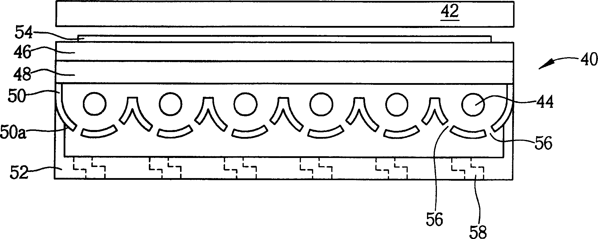
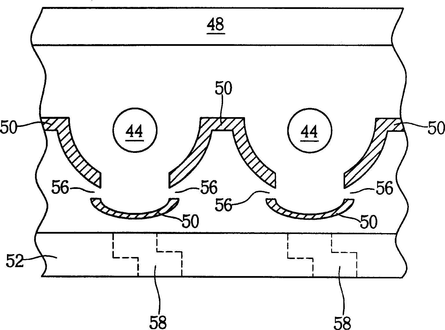
[0014] Please refer to figure 2 , figure 2 It is a schematic cross-sectional view of the backlight module 40 according to the first embodiment of the present invention. Such as figure 2 As shown, the backlight module 40 is arranged under the display screen 42, and the backlight module 40 includes at least one light source generator 44, a diffusion plate 46 arranged between the light source generator 44 and the display screen 42, and a diffuser plate 46 arranged between the light source generator 44 and the The light guide plate 48 between the device 44 and the diffuser plate 46, a reflective plate 50 disposed under the light source generator 44, and a reflective plate 50 disposed under the reflective plate 50 are used to wrap around the reflective plate 50 and have a plurality of first heat dissipation Housing 52 with holes 58 .

[0015] Generally speaking, the light source generator 44 is constituted by a lamp tube for providing a light source (not shown). In a preferr...


PUM


Abstract

The back light assembly set below the display screen includes at least one light source generator, one diffusion board, one light guiding board and one reflecting board. The diffusion board is used to diffuse light from the light source generator to the display screen, the light guiding board is used to diffuse the light to the diffusion board, and the reflecting board is used to reflect the light to the light guiding board and has at least one opening for exhausting heat the light source generator in the back light assembly produces.

Description

technical field [0001] The present invention provides a back light module, especially a back light module with high heat transfer rate. Background technique [0002] Backlight module is one of the key components of liquid crystal display products, and has been widely used in digital cameras, digital personal assistants (PDA), satellite navigation systems, computer monitors and flat-screen TVs. Generally speaking, the backlight module is arranged under a display panel, and has a light source and a diffusing plate, so as to provide a uniformly diffused light to the display panel, and then control the display panel On the pixel electrode to form the appropriate image. Among them, the backlight module can be divided into direct illuminance backlight module whose light source is directly below the display screen or edge light backlight module with light source near the side of the display screen according to the location of the light source. . Since the direct-lit backlight mo...

Claims


Application Information

Patent Timeline
Patent Type & Authority Applications(China)
IPC IPC(8): G02B5/02G02F1/1335
Inventor 麦哲魁
Owner TPO DISPLAY
Why Eureka
Try Eureka