A Subsurface Structure Inversion Imaging Method

A technology of underground structure and reflection coefficient, which is applied in the field of oil and gas geophysical exploration engineering, can solve problems affecting imaging quality, etc., and achieve the effects of improving imaging accuracy, reducing interference, and improving efficiency

Inactive Publication Date: 2019-05-07
CHINA UNIV OF PETROLEUM (EAST CHINA)
View PDF6 Cites 0 Cited by
  • Summary
  • Abstract
  • Description
  • Claims
  • Application Information

AI Technical Summary

Problems solved by technology

However, when processing multi-source data, the crosstalk noise generated by the cross-correlation of the wave fields of uncorrelated shots cannot effectively suppress the crosstalk noise, which ultimately affects the imaging quality.

Method used


Image

  • A Subsurface Structure Inversion Imaging Method
  • A Subsurface Structure Inversion Imaging Method
  • A Subsurface Structure Inversion Imaging Method

Examples


Embodiment 1

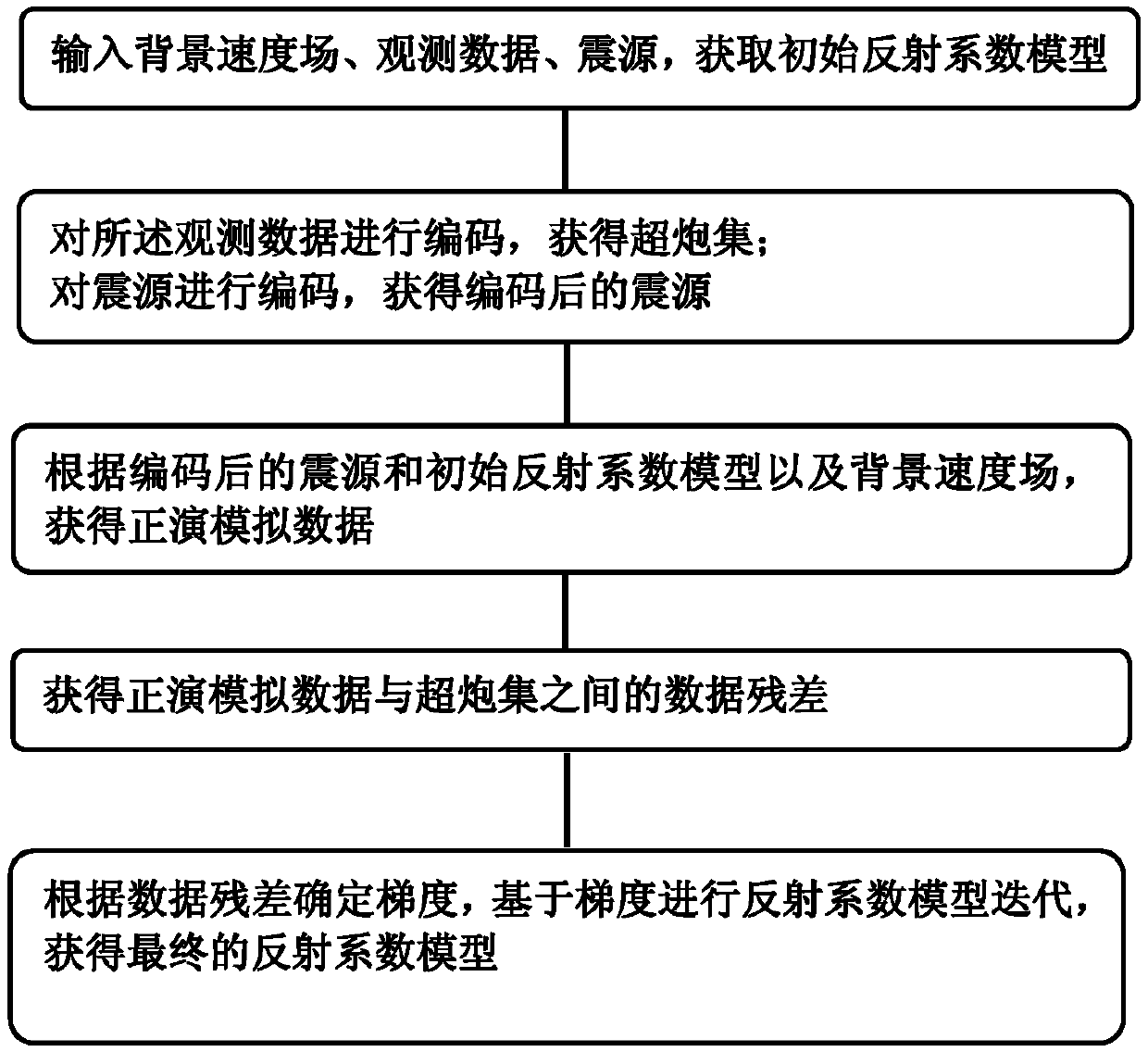
[0023] Embodiment 1 of the present invention: a subterranean structure inversion imaging method, such as figure 2 shown, including the following steps:

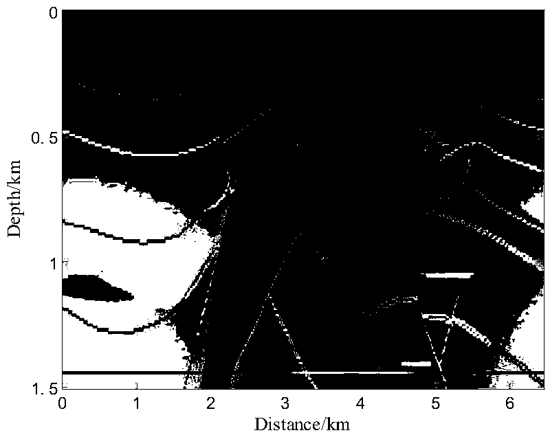
[0024] S1, input the background velocity field, observation data and source. In practice, according to the needs, the observation data is often multi-source data collected by multiple sources, for example, the method of the present invention is applied to the international standard salt dome model, image 3 is the background velocity field of the salt dome model; using the Bonn forward modeling to obtain single-shot data such as Figure 4 , the initial reflection coefficient model is obtained according to the background velocity field, observation data and seismic source.

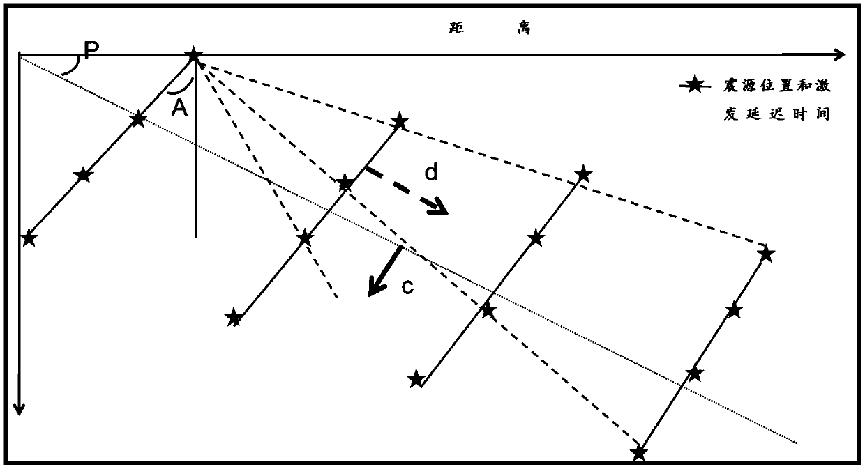
[0025] S2. Encoding the observation data to obtain a super shot set; encoding the seismic source to obtain the encoded seismic source. That is to say, the shot set is coded by segmented stepped plane waves to form a coded super shot set D obs , in the...


PUM


Abstract

The invention discloses an underground structure inversion imaging method, which comprises the following steps: S1) inputting background velocity field, observation data and a seismic source, and obtaining an initial reflection coefficient model; S2) carrying out encoding on the observation data to obtain a super shot gather, and carrying out encoding on the seismic source to obtain an encoded seismic source; S3) obtaining forward modeling data according to the encoded seismic source and the initial reflection coefficient model; S4) obtaining data residual between the forward modeling data and the super shot gather; and S5) according to the data residual, determining the gradient, and carrying out reflection coefficient model iteration based on the gradient to obtain a final reflection coefficient model. By carrying out segmented step coding on the observation data and the seismic source, difference between multi-seismic resource shot data is increased fully, interference between adjacent shots is reduced, crosstalk noise is suppressed well during multi-seismic resource shot data imaging, and imaging precision during multi-seismic resource shot data imaging inversion is improved.

Description

technical field [0001] The invention relates to an underground structure inversion imaging method, which belongs to the field of oil and gas geophysical prospecting engineering. Background technique [0002] In the current field of exploration, underground data acquisition technology is particularly critical. Among them, the multi-source data acquisition method has begun to attract attention. The so-called multi-source data means that multiple sources are excited at the same time. The wave field propagates in the underground medium and the data received on the ground. It is the subsurface medium's response to multiple seismic sources. The multi-source data acquisition method improves the problem of insufficient lighting in the traditional acquisition method, and also greatly reduces the cost of 3D data acquisition. However, when processing multi-source data, the crosstalk noise generated by the cross-correlation of the wave fields of uncorrelated shots cannot effectively su...

Claims


Application Information

Patent Timeline
Patent Type & Authority Patents(China)
IPC IPC(8): G01V1/34
CPCG01V1/345G01V2210/62G01V2210/74
Inventor 国运东李振春黄建平崔超李庆洋李闯
Owner CHINA UNIV OF PETROLEUM (EAST CHINA)
Why Eureka
Try Eureka