Outer surface defect detection method and device for cylindrical workpiece

A defect detection, cylindrical technology, applied in the direction of optical testing flaws/defects, etc., can solve the problem of inaccurate detection results of photographing effects, and achieve the effect of avoiding accidental and accurate defect analysis results.

Active Publication Date: 2017-10-10
广东嘉铭智能科技有限公司
View PDF17 Cites 14 Cited by
  • Summary
  • Abstract
  • Description
  • Claims
  • Application Information

AI Technical Summary

Problems solved by technology

[0004] The embodiment of the present invention provides a method and device for detecting defects on the outer surface of a cylindrical workpiece, which is used to rotate the cylindrical workpiece and simultaneously use an area array camera to take pictures of the outer surface of the cylindrical workpiece, and synthesize several photos taken into a 360-degree Image, and then analyze the defect, which solves the problem that the existing line-scan camera combined with the strip light source detection method for defects such as relatively shallow smooth transition pits and defects perpendicular to the direction of the light strip, the existing workpieces are in the process of rotating and taking pictures The position change will seriously affect the photo effect and cause the technical problem of inaccurate detection results.

Method used


Image

  • Outer surface defect detection method and device for cylindrical workpiece
  • Outer surface defect detection method and device for cylindrical workpiece
  • Outer surface defect detection method and device for cylindrical workpiece

Examples


no. 1 example

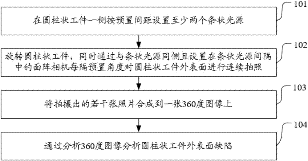
[0045] see figure 1 , the embodiment of the present invention provides a first embodiment of a method for detecting defects on the outer surface of a cylindrical workpiece, including:

[0046] 101. Set at least two strip light sources at a preset distance on one side of the cylindrical workpiece;

[0047] In the embodiment of the present invention, firstly, at least two strip light sources need to be set on one side of the cylindrical workpiece according to a preset distance. Just set an appropriate number of strip light sources.

[0048] 102. Rotate the cylindrical workpiece, and at the same time take continuous pictures of the outer surface of the cylindrical workpiece at preset angles through an area array camera on the same side as the strip light source and arranged in the interval of the strip light source;

[0049] In the embodiment of the present invention, after setting at least two bar-shaped light sources at a preset distance on one side of the cylindrical workpie...

no. 2 example

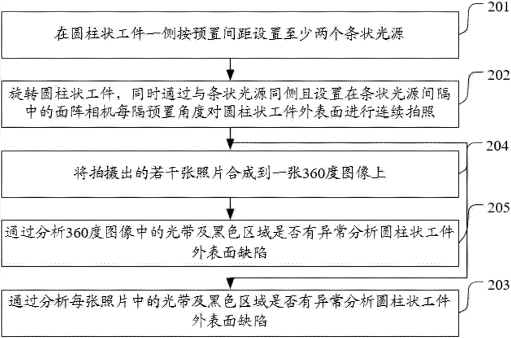
[0054] see figure 2, the embodiment of the present invention provides a second embodiment of a method for detecting defects on the outer surface of a cylindrical workpiece, including:

[0055] 201, setting at least two strip light sources at a preset distance on one side of the cylindrical workpiece;

[0056] In the embodiment of the present invention, firstly, at least two strip light sources need to be arranged on one side of the cylindrical workpiece at a preset distance.

[0057] 202. Rotate the cylindrical workpiece, and at the same time take continuous pictures of the outer surface of the cylindrical workpiece at preset angles through an area array camera on the same side as the strip light source and arranged in the interval of the strip light source;

[0058] In the embodiment of the present invention, after setting at least two bar-shaped light sources at a preset distance on one side of the cylindrical workpiece, it is necessary to rotate the cylindrical workpiece,...


PUM


Abstract

The embodiment of the invention discloses an outer surface defect detection method and an outer surface defect detection device for a cylindrical workpiece, used for rotating the cylindrical workpiece and shooting the outer surface of the cylindrical workpiece by using an area array camera, combining the a plurality of shot photos into a 360-degree image, and then analyzing the defect; therefore, the technical problem that in an existing defect detection method by using a line scan camera cooperated with a strip-shaped light source, a detection result is inaccurate due to the fact that the shooting effect is seriously influenced by position variation of the workpiece during a rotary shooting process when the method is used for detecting smoothly transited shallow pits and the defects perpendicular to a light band direction.

Description

technical field [0001] The invention relates to the field of workpiece detection, in particular to a method and device for detecting defects on the outer surface of a cylindrical workpiece. Background technique [0002] There are many cylindrical workpieces in industrial products, such as shafts, copper sleeves, cylinder liners, bullet casings, etc. It is necessary to inspect their appearance to detect various processing defects, such as pits, cracks, cracks, scratches, deformation, etc. . [0003] The existing inspection method for cylindrical workpieces is to use a strip light source to irradiate the surface of cylindrical workpieces, and then use a line-scan camera to take pictures while rotating the workpieces. However, for some defects such as relatively shallow pits with smooth transitions and In the detection of directional defects, the position change of the workpiece during the rotation and photographing process will seriously affect the photographing effect, resul...

Claims


Application Information

Patent Timeline
Patent Type & Authority Applications(China)
IPC IPC(8): G01N21/89
CPCG01N21/89
Inventor 劳永革段峰何建枝
Owner 广东嘉铭智能科技有限公司
Why Eureka
Try Eureka