Frame body for bridge pier stress detection device
A detection device and bridge pier technology, applied in measuring devices, force/torque/work measuring instruments, instruments, etc., can solve problems such as bridge collapse, impact on vehicles, pedestrian safety, bridge collapse, etc.
- Summary
- Abstract
- Description
- Claims
- Application Information
AI Technical Summary
Problems solved by technology
Method used
Image
Examples
Embodiment 1
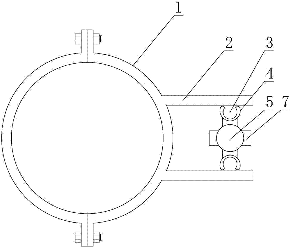
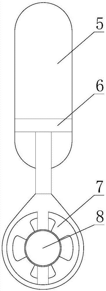
[0022] like figure 1 and figure 2 As shown, a frame body for a bridge pier force detection device includes a hoop body 1 in the shape of a hoop, the hoop body 1 is provided with a mounting plate 2, and a strip-shaped guide rod is fixed on the mounting plate 2 3. The length direction of the guide rod 3 is parallel to the axis direction of the hoop body 1 .
[0023] This scheme is suitable for the installation of the power supply device of the detection device for detecting the force of the bridge pier in the following form. The power supply device includes a generator 8 and a water wheel 7 connected to the mechanical energy input end of the generator 8. The water When the wheel 7 rotates, it is used to drive the mechanical energy input end of the generator 8 to rotate; it also includes a floating body 5 and a hanger 6, the upper end of the hanger 6 is fixedly connected with the floating body 5, and the lower end of the hanger 6 is fixedly connected with the power supply devic...
Embodiment 2
[0026] like figure 1 and figure 2 As shown, this embodiment is further limited on the basis of Embodiment 1: in order to enable the guide groove 4 to slide between the two ends of the guide rod 3 along the length direction of the guide rod 3, the guide rod 3 is close to the mounting plate One side of 2 is fixedly connected with mounting plate 2. In this solution, the corresponding guide groove 4 is set as an open groove, and the opening part of the guide groove 4 can cross the connection point between the guide rod 3 and the mounting plate 2.
[0027] In order to prevent the guide groove 4 from rotating with the guide rod 3 as the rotating shaft and reduce the shaking of the water wheel 7 and other parts during work, the number of the guide rods 3 is two, and the two guide rods 3 are parallel to each other. In this solution, preferably, the corresponding guide grooves 4 are arranged on the floating body 5 , and the two guide grooves 4 are located on different sides of one o...
PUM
 Abstract
Description
Claims
Application Information
 - R&D
- Intellectual Property
- Life Sciences
- Materials
- Tech Scout
- Unparalleled Data Quality
- Higher Quality Content
- 60% Fewer Hallucinations
Browse by: Latest US Patents, China's latest patents, Technical Efficacy Thesaurus, Application Domain, Technology Topic, Popular Technical Reports.
© 2025 PatSnap. All rights reserved.Legal|Privacy policy|Modern Slavery Act Transparency Statement|Sitemap|About US| Contact US: help@patsnap.com


