
Mounting frame for bridge pier stress monitoring component power supply device

A force monitoring and power supply technology, applied in the direction of electromechanical devices, electrical components, electric components, etc., can solve problems such as bridge collapse, affecting vehicles, pedestrians passing safely, bridge collapse, etc.

Inactive Publication Date: 2018-04-06
成都泰利崃贸易有限公司
View PDF1 Cites 0 Cited by
  • Summary
  • Abstract
  • Description
  • Claims
  • Application Information

AI Technical Summary

Problems solved by technology

[0003] When the bridge is designed, it is safe for the normal support of the bridge to be under a certain range of scouring force, but the excessive rise of the water level or / and the acceleration of the water speed will affect the safe passage of vehicles and pedestrians on it, and the installation will cause the bridge to collapse. In technology, there is also no shortage of accidents where bridges collapse when vehicles pass through bridges due to floods

Method used


Image

  • Mounting frame for bridge pier stress monitoring component power supply device
  • Mounting frame for bridge pier stress monitoring component power supply device

Examples


Embodiment 1

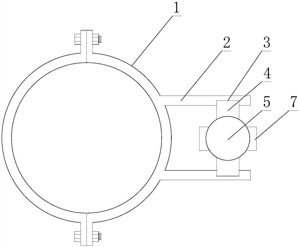
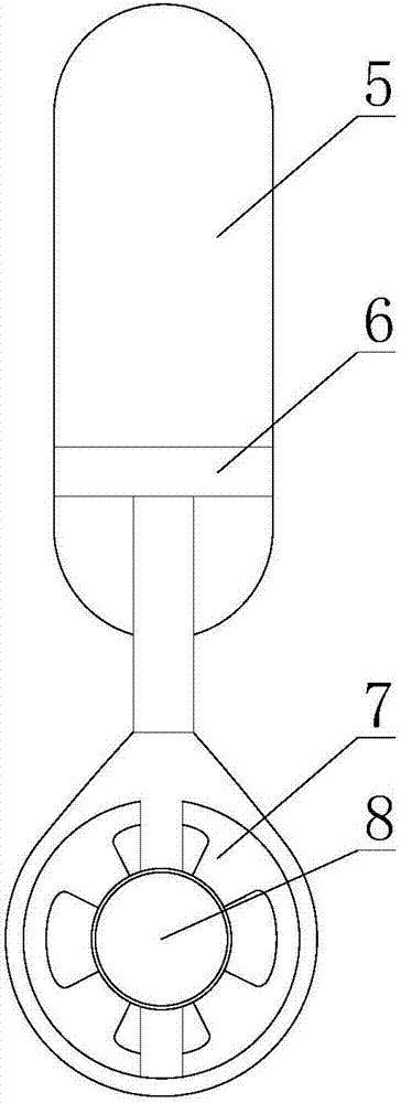
[0021] Such as figure 1 and figure 2 As shown, a mounting frame for the power supply device of the force monitoring component of the bridge support pier, including the power supply device, including a hoop body 1 in the shape of a hoop, and two mounting brackets in a positive relationship are arranged on the hoop body 1. Plates 2, guide grooves 3 are provided on the inner side of each mounting plate 2, and the guide grooves 3 are parallel to each other.

[0022] This scheme is applicable to the installation of the electric energy supply device of following form, and electric energy supply device comprises generator 8 and the water wheel 7 that is connected on the mechanical energy input end of generator 8, and described water wheel 7 is used for driving generator 8 when rotating The mechanical energy input end rotates; it also includes a floating body 5 and a hanger 6, the upper end of the hanger 6 is fixedly connected to the floating body 5, and the lower end of the hanger ...

Embodiment 2

[0025] Such as figure 1 and figure 2 As shown, this embodiment is further limited on the basis of Embodiment 1: in order to facilitate the insertion of the power supply device into the guide groove 3 , the respective upper ends of the guide grooves 3 intersect with the upper ends of the corresponding mounting plates 2 .

[0026] In order to reduce the resistance during the rising and sinking process of the power supply device, the respective length directions of the guide grooves 3 are located in the vertical direction.

[0027] In order to make this solution have ideal anti-corrosion performance, the surfaces of the hoop body 1 and the mounting plate 2 are coated with an anti-corrosion layer.

[0028] In order to make this program work, the frictional resistance of the parts with sliding friction is small, and can maintain good anti-corrosion performance for a long time, the anti-corrosion layer in the guide groove 3 is a polytetrafluoroethylene plate lined on the groove su...


PUM


Abstract

The invention discloses a mounting frame for a bridge pier stress monitoring component power supply device. The mounting frame comprises a hoop body presenting an embracing hoop shape. Two opposite mounting boards are set on the hoop body. A guide slot is set at the inner side of each mounting board. The guide plates are mutually parallel. The mounting frame is convenient for mounting, the mechanical property of a bridge pier is influenced a little, and moreover, the reliable power supply is provided for a monitoring component by a power supply device.

Description

technical field [0001] The invention relates to the technical field of force detection devices for road and bridge support piers, in particular to a mounting frame for a power supply device for force monitoring components of bridge support piers. Background technique [0002] Most of the bridges are built on the river, and the scouring force of the river on the bridge pier is an important parameter of the pier's stress during the use of the bridge pier, and the water level and flow velocity of the river have a great influence on the scouring force. In summer, every flood season, the water level of the river rises sharply, and the scouring force of the river water on the bridge piers increases. The above scouring force has an important impact on the supporting performance of the bridge. [0003] When the bridge is designed, it is safe for the normal support of the bridge to be under a certain range of scouring force, but the excessive rise of the water level or / and the accele...

Claims


Application Information

Patent Timeline
Patent Type & Authority Applications(China)
IPC IPC(8): H02K5/00H02K7/18
CPCH02K5/00H02K7/1823
Inventor 敬天江
Owner 成都泰利崃贸易有限公司
Learn More