Supercharge Your Innovation With Domain-Expert AI Agents!

Cyclone separator

A technology of cyclone separator and separation structure, which is applied to cyclone devices, devices whose axial directions of cyclone can be reversed, etc. problems, to achieve the effect of improved effect, high purity, and short airflow path

Pending Publication Date: 2017-10-13
杭州富阳优信科技有限公司
View PDF7 Cites 0 Cited by
  • Summary
  • Abstract
  • Description
  • Claims
  • Application Information

AI Technical Summary

Benefits of technology

The present technology relates to an apparatus for separating solids from gases by utilizing cyclones that use acceleration structures at their sides or just one separated section within them. This allows more efficient gas movement while improving the quality of the resulting product.

Problems solved by technology

The technical problem addressed in this patented technology relates to improving the performance of cyclones for removing small particulate matter (PM) such as mist and smoke during industrial processes involving gases like natural gas and oil.

Method used


Image

  • Cyclone separator
  • Cyclone separator
  • Cyclone separator

Examples


Embodiment Construction

[0019] The following are specific embodiments of the present invention, and the technical solution of the present invention will be further described with reference to the accompanying drawings.

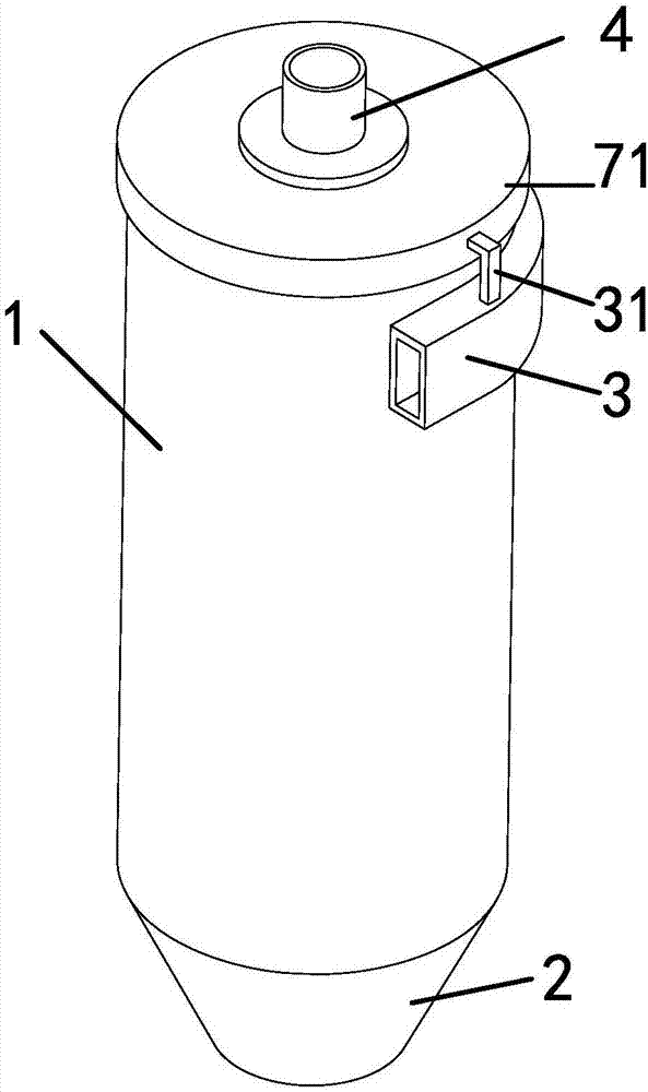
[0020] Such as figure 1 As shown, the cyclone separator includes a cylindrical body 1 and a cone 2 arranged below the cylindrical body 1. An inlet pipe 3 is provided on the upper end side of the cylindrical body 1, and an outlet pipe is provided on the top of the cylindrical body 1. In the air duct 4, the inner wall of the cylinder 1 is provided with an accelerating separation structure for accelerating the separation of solid particles.

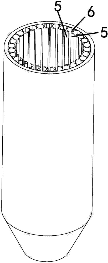
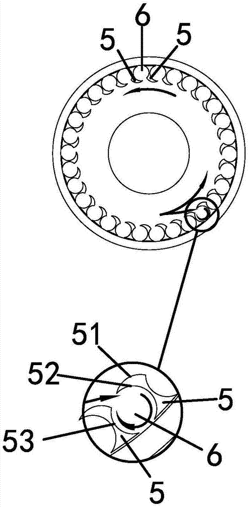
[0021] Specific acceleration separation structure such as figure 2 As shown, the accelerating separation structure includes bar-shaped stop bars 5 arranged along the axis of the cylindrical body 1. There are multiple stop bars 5 and are evenly distributed along the circumferential direction of the cylinder body 1. The gap forms a downward channel 6 for...


PUM


Abstract

The invention provides a cyclone separator, and belongs to the technical field of machines. The cyclone separator solves the problem that according to an existing cyclone separator, when gas is at high speed, solid particles can enter top spin airflow, and consequently the separation effect is not good. The cyclone separator comprises a cylinder and a cone arranged below the cylinder. An air inlet pipe is arranged at the side portion of the upper end of the cylinder, an air outlet pipe is arranged on the top of the cylinder, and a separation accelerating structure accelerating solid particle separation is arranged on the inner side wall of the cylinder. Through the separation structure on the side wall, bottom spinning airflow continuously spins downwards along the surface of the separation accelerating structure, bottom spinning airflow is formed on the bottom cone, and pure airflow is discharged at the air outlet pipe.

Description


Claims


Application Information

Patent Timeline
Owner 杭州富阳优信科技有限公司
Features
  • R&D
  • Intellectual Property
  • Life Sciences
  • Materials
  • Tech Scout
  • Unparalleled Data Quality
  • Higher Quality Content
  • 60% Fewer Hallucinations
Learn More