Coding speedometer detection device and method based on servo control technology
A technology of servo control and detection device, applied in measuring devices, instruments, etc., can solve the problems of long detection period, inability to determine the cause of failure, inability to detect multiple photosensitive elements at the same time, etc. Effect
Active Publication Date: 2017-10-13
CASCO SIGNAL
View PDF4 Cites 6 Cited by
- Summary
- Abstract
- Description
- Claims
- Application Information
AI Technical Summary
Problems solved by technology
[0005]
1. It can only detect whether the photosensitive element has output, but cannot confirm whether the output meets the requirements
[0006]
2. It is impossible to detect multiple photosensitive elements on a coded odometer at the same time, and then it is impossible to calculate whether the phase difference of each photosensitive element meets the requirements
[0007]
3. Unable to determine the cause of the failure, such as determining which photosensitive element is faulty or the code disc is faulty
[0008]
4. The detection cycle is long, and the installation and debugging structure is complicated
Method used
View moreImage
Smart ImageViewing Examples
Examples
specific Embodiment
[0072] A coded odometer detection process based on servo control technology, the process includes the following steps:
[0073] Step 1, modify the configuration file of the program, initialize the detected device, the number of gaps W of the encoding disc, the number S of photosensitive elements installed, and the type of photosensitive sensor (Red red, Black black, Blue blue);
Login to View More PUM
 Abstract
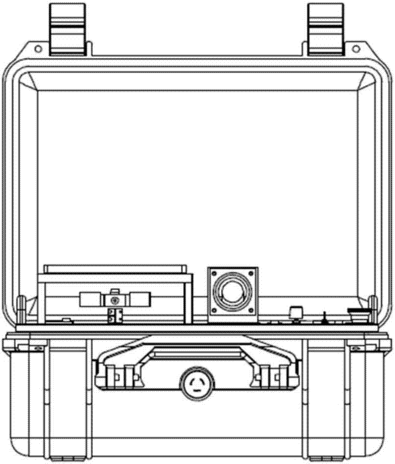
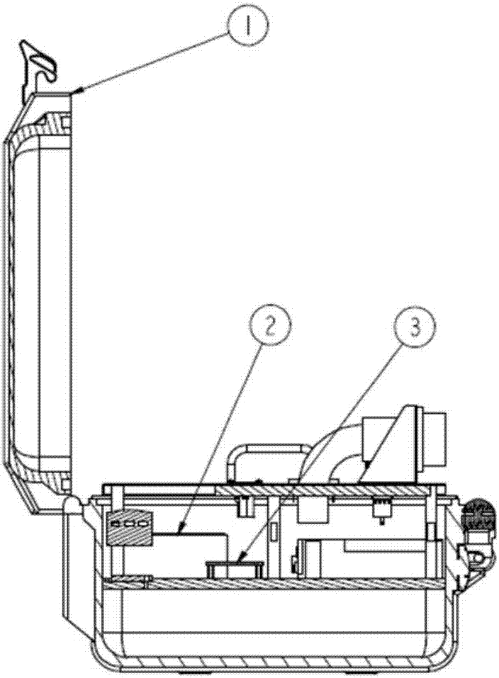
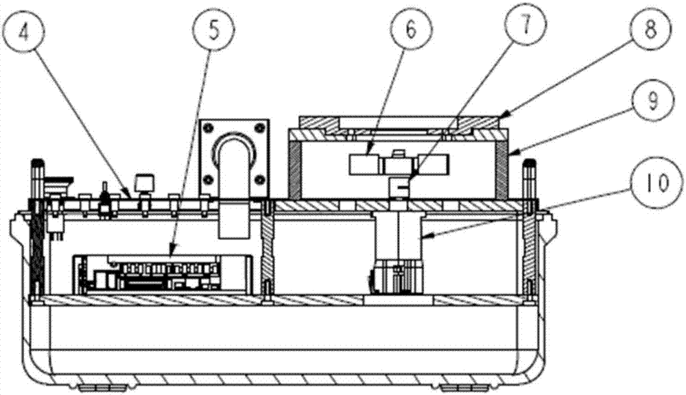
The invention relates to a coding speedometer detection device and method based on a servo control technology. The coding speedometer detection device comprises a box body and a detector mounted on the box body, wherein the detector comprises a control panel, a servo motor, a motor controller, a data acquisition card and a coding speedometer driving bracket; the control panel is connected with the motor controller and the data acquisition card respectively; the data acquisition card is connected with a coding speedometer to be detected; the motor controller is connected with the servo motor; the servo motor drives the coding speedometer to move through the coding speedometer driving bracket. Compared with the prior art, the coding speedometer detection device and method based on the servo control technology can be used or measuring whether all photosensitive elements on one coding speedometer have normal output or not at the same time.
Description
technical field [0001] The invention relates to coded odometer detection technology, in particular to a coded odometer detection device and method based on servo control technology. Background technique [0002] In rail traffic signal equipment, coded odometer is a device specially designed to meet the needs of rail operation. The motion state of the vehicle can be obtained in real time through the feedback information of the coded odometer, so as to calculate the safety range of the vehicle. Especially in the CBTC system, the motion state of the vehicle is crucial to the safety of the vehicle operation. [0003] Inside the coded odometer, there is a coded disc that is connected with the diameter of the warp shaft and rotates synchronously, and several photosensitive elements fixed along the circumference of the coded disc are activated. When the coded odometer moves with the wheel diameter of the vehicle, the continuous beam emitted by the emitting diode is blocked by the ...
Claims
Login to View More Application Information
Patent Timeline
 Patent Type & Authority Applications(China)
IPC IPC(8): G01C25/00G01D18/00
CPCG01C25/00G01D18/00Y02P90/02
Inventor 查伟邹宏峰汪小勇杜岳升李付军刘锦峰徐烨袁静
Owner CASCO SIGNAL
Features
- R&D
- Intellectual Property
- Life Sciences
- Materials
- Tech Scout
- Unparalleled Data Quality
- Higher Quality Content
- 60% Fewer Hallucinations
Learn More Browse by: Latest US Patents, China's latest patents, Technical Efficacy Thesaurus, Application Domain, Technology Topic, Popular Technical Reports.
© 2025 PatSnap. All rights reserved.Legal|Privacy policy|Modern Slavery Act Transparency Statement|Sitemap|About US| Contact US: help@patsnap.com


