
Seat Locking Structure

A locking structure and seat technology, which is applied to vehicle seats, special positions of vehicles, vehicle components, etc., can solve the problems of complex locking structure and assembly, and achieve the effect of eliminating dimensional deviation and preventing slippage.

Active Publication Date: 2019-03-22
KEIPER (CHANGSHU) SEATING MECHANISMS CO LTD
View PDF6 Cites 0 Cited by
  • Summary
  • Abstract
  • Description
  • Claims
  • Application Information

AI Technical Summary

Problems solved by technology

[0007] Aiming at the problems of complex seat locking structure and complex assembly in the prior art, the present invention provides a seat locking structure, which is arranged on the backrest of the rear seat of the car, including a lock tongue, a pull rod, a cover and a reset part ;

Method used


Image

  • Seat Locking Structure
  • Seat Locking Structure
  • Seat Locking Structure

Examples


Embodiment Construction

[0036] In the following description, numerous specific details are given in order to provide a more thorough understanding of the present invention. It will be apparent, however, to one skilled in the art that the present invention may be practiced without one or more of these details. In other examples, some technical features known in the art are not described in order to avoid confusion with the present invention.

[0037] In order to thoroughly understand the present invention, detailed steps and detailed structures will be provided in the following description, so as to illustrate the technical solution of the present invention. Preferred embodiments of the present invention are described in detail below, however, the present invention may have other embodiments besides these detailed descriptions.

[0038] The present invention provides a seat locking structure, which is arranged on the backrest of the rear seat of the car, and includes a lock tongue 30, a pull rod 40, ...


PUM


Abstract

The invention provides a seat lock-up structure. The seat lock-up structure is arranged on a backrest of a rear seat of a vehicle. The seat lock-up structure comprises a lock tongue, a pull rod, a cover cap and a reset part. The lock tongue is installed in the caver cap. A riveting hole is formed in the end surface of the cover cap. An installing hole which corresponds to the riveting hole is formed in the contacting end surface of the lock tongue and the cover cap. The reset part penetrates through the installing hole formed in the end surface of the lock tongue and is fixed through the riveting hole of the cover cap. A movable groove is formed in the lock tongue. The bottom of the pull rod extends into the movable groove. The cover cap is provided with a sliding groove which is used for allowing a steel wire of a vehicle body to move. The bottom of the lock tongue is further provided with a lock-up opening groove. The reset part and the lock tongue are installed together. The lock tongue can rotate centering on the reset part. By means of the reset part, the lock tongue can be kept resetting without external force. Compared with a traditional seat lock-up structure, the seat lock-up structure is simple in structure, components such as a locking piece, a rubber block and a lower shell body of the traditional lock-up structure are omitted, and the component cost is grammatically reduced.

Description

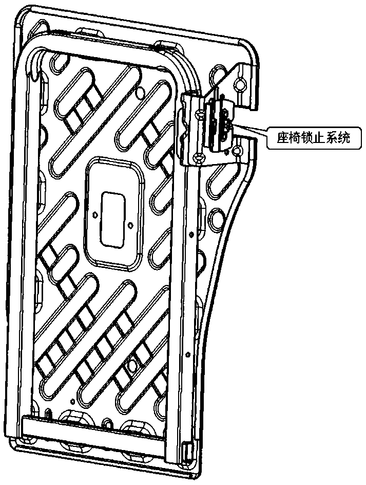
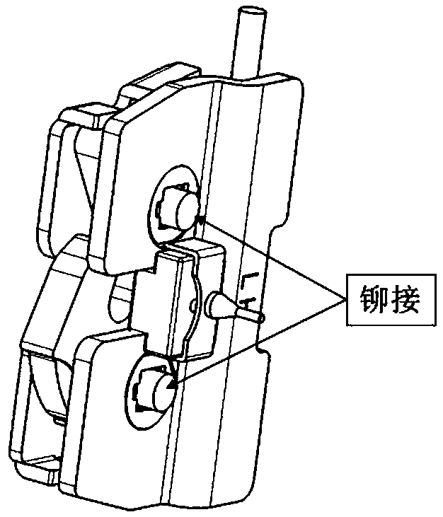
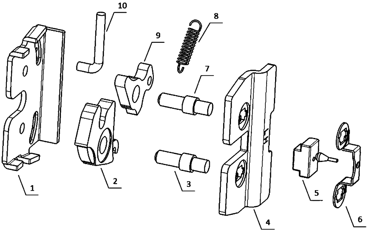
technical field [0001] The invention relates to the field of automobile seat manufacturing, in particular to a seat locking structure. Background technique [0002] When the backrest of the car seat needs to be folded down, it needs to be realized through the seat locking system. The locking system is usually arranged on the seat back, such as figure 1 shown. [0003] refer to Figure 2-3 As shown, the existing car seat locking system application scheme is as follows: [0004] The seat locking system usually includes: lower cover plate 1, lock tongue 2, support shaft (for supporting the lock tongue) 3, upper cover plate 4, rubber block 5, bracket 6, support shaft (for supporting the locking plate 9 ) 7, extension spring 8, locking plate 9, pull rod 10. [0005] At present, there is an assembly process of an automobile seat locking system: the rubber block 5 and the bracket 6 are pre-assembled. Pass the two support shafts 3 & 7 through the upper cover 4 and insert them ...

Claims


Application Information

Patent Timeline
Patent Type & Authority Patents(China)
IPC IPC(8): B60N2/90
Inventor 唐韵华付小广唐臻毅
Owner KEIPER (CHANGSHU) SEATING MECHANISMS CO LTD
Learn More