Display substrate and display device

A display substrate and display area technology, applied in the direction of instruments, semiconductor devices, optics, etc., can solve the problems of jagged edges and uneven arrangement positions of the AA area, and achieve the effect of reducing acuity

Inactive Publication Date: 2017-10-17
BOE TECH GRP CO LTD +1
View PDF9 Cites 43 Cited by
  • Summary
  • Abstract
  • Description
  • Claims
  • Application Information

AI Technical Summary

Problems solved by technology

[0004] However, although the edge of the above-mentioned AA area is a curve macroscopically, microscopically, the rectangular sub-pixels 10 at the edge of the AA area have jagged edges due to uneven arrangement positions.

Method used


Image

  • Display substrate and display device
  • Display substrate and display device
  • Display substrate and display device

Examples


Embodiment Construction

[0039] The following will clearly and completely describe the technical solutions in the embodiments of the present invention with reference to the accompanying drawings in the embodiments of the present invention. Obviously, the described embodiments are only some, not all, embodiments of the present invention. Based on the embodiments of the present invention, all other embodiments obtained by persons of ordinary skill in the art without making creative efforts belong to the protection scope of the present invention.

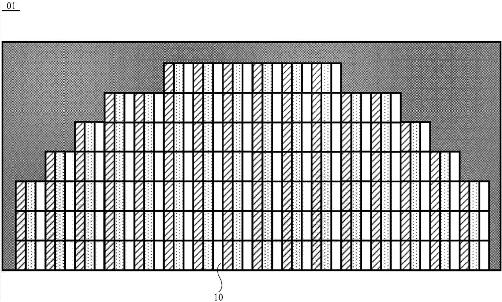
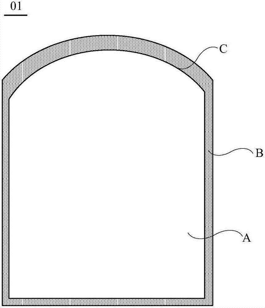
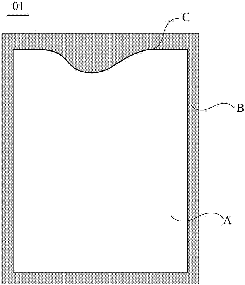
[0040] An embodiment of the present invention provides a display substrate 01, such as figure 2 or image 3 As shown, the display substrate 01 is provided with a display area A and a non-display area B located around the display area A. Wherein, at least a part of the edge of the above-mentioned display area A is a special-shaped edge C having a concave-convex shape, that is, the special-shaped edge is in a non-linear state.

[0041] specific, figure 2 Th...


PUM


Abstract

The embodiment of the invention provides a display substrate and a display device and relates to the technical field of display. The display substrate and the display device are used for solving the problem that the saw tooth effect appears in the edge of an AA area during display when the edge of the AA area is in a non-linear state. The display substrate comprises a black matrix. The display substrate is provided with a display area, and at least part of the edge of the display area is a special-shaped edge in a concave-convex shape. In the display area, the black matrix consists of a plurality of shading bars arranged in a criss-cross mode, so that a plurality of sub pixels arranged in a matrix mode are defined. A visual weakening region near the special-shaped edge is arranged in the display area. In the visual weakening area, the black matrix also comprises shading blocks located in the sub pixels, and the shading blocks occupy part of the sub pixels area. The display substrate is used for display.

Description

technical field [0001] The present invention relates to the field of display technology, in particular to a display substrate and a display device. Background technique [0002] With the continuous development of display technology, users have higher and higher requirements on the appearance or integration performance of the display substrate. Therefore, in order to meet the needs of users, the edge of AA (Active Area, effective display area) of the display substrate needs to be non-linear. In this way, the above-mentioned AA area can meet the requirements of diversified edge shapes of the display substrate. In addition, some other components, such as an earpiece or a camera, can also be integrated in the recessed portion on the edge of the above-mentioned AA area. [0003] In the existing technology, such as figure 1 As shown, there are rectangular sub-pixels 10 in the region AA of the display substrate 01 . In this case, in order to make the edge of the AA area non-linea...

Claims


Application Information

Patent Timeline
Patent Type & Authority Applications(China)
IPC IPC(8): G02F1/1335
CPCG02F1/133512G02F2201/52G02F2201/56G02F2203/30G02F1/136209H01L27/1248
Inventor 王大威王甲强刘蕊任健穆景飞张彦超王彦明金海玲蔡修军
Owner BOE TECH GRP CO LTD
Why Eureka
Try Eureka