Tibial/humeral intramedullary nail and tibial group and humeral group using tibial/humeral intramedullary nail

A technique for the tibial group and the tibia, which is applied in the direction of internal fixators, internal bone synthesis, fixers, etc., can solve the problems of poor anti-rotation, small application range, and small self-locking force, so as to improve safety and effectiveness, shorten the The effect of reducing the installation time and difficulty of installation

Active Publication Date: 2017-10-20
JIAOZUO XINGANG MEDICAL EQUIP
View PDF5 Cites 0 Cited by
  • Summary
  • Abstract
  • Description
  • Claims
  • Application Information

AI Technical Summary

Benefits of technology

This invention relates to an improved orthopedic implant called this type of nails or pins used for fixing fractured parts together. These nails have a special design made by combining two materials: one material forms part of the main body of these tools (the cortex) and another material on top. When they are fixed into place, there will also hold them securely enough to prevent movement when subjected to stress such as weight bearing. By doing things like making sure each component fits properly without requiring any other devices attached, the risk of surgery can decrease due to reduced costs associated with installing conventional methods. Additionally, if the components become loose after being installed, less invasive procedures may still work well even more safely than those performed through openings at their ends. Overall, this new tool provides technical benefits over existing techniques but requires no extra equipment compared to current options.

Problems solved by technology

This patented technical problem addressed by the present inventor relates to an improved type of device used for treating fractures caused by osteoporotic compression syndrome (OCS). Current methods involve inserting stainless steel pins into holes drilled directly across the damaged portion of the spine with multiple steps involving drilling and countersinking each hole separately before attaching new anchors. These techniques have drawbacks such as difficulty ensuring accurate placement due to weaknesses like muscle fibers surrounding the joint being treated, potential injury from sharp instruments during insertion, lack of precision control over how well these procedures work, and potentially harmful side effects associated with prolonged use of metal tools.

Method used


Image

  • Tibial/humeral intramedullary nail and tibial group and humeral group using tibial/humeral intramedullary nail
  • Tibial/humeral intramedullary nail and tibial group and humeral group using tibial/humeral intramedullary nail
  • Tibial/humeral intramedullary nail and tibial group and humeral group using tibial/humeral intramedullary nail

Examples


Embodiment Construction

[0019] Specific embodiments of the present invention will be described in further detail below based on the accompanying drawings. It should be understood that the description of the embodiments of the present invention here is not intended to limit the protection scope of the present invention.

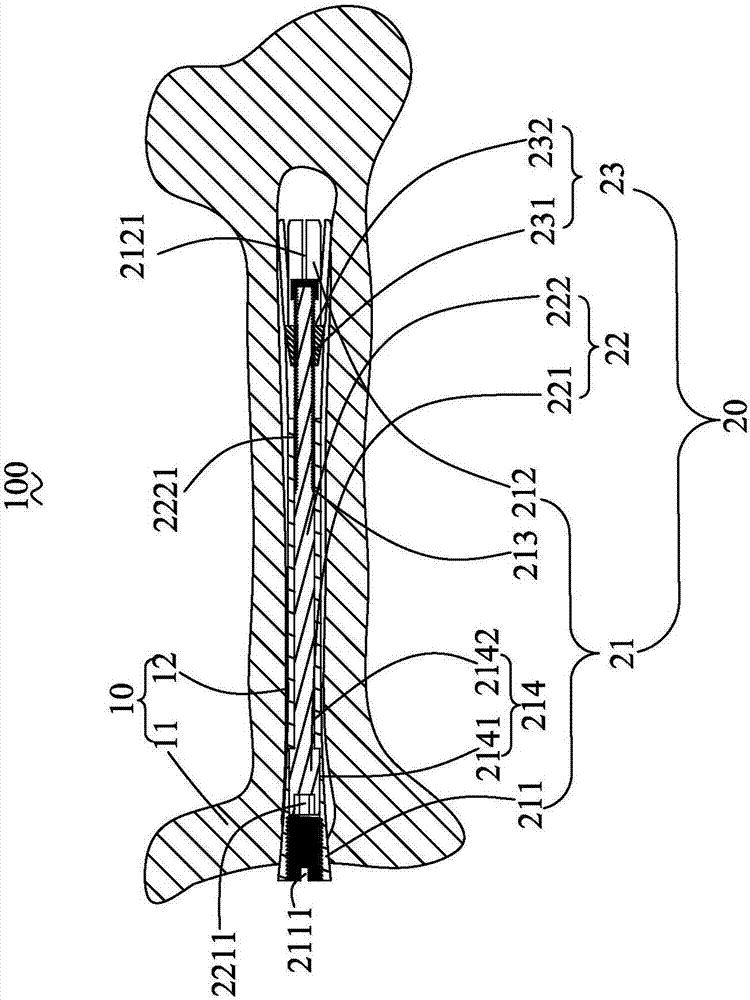
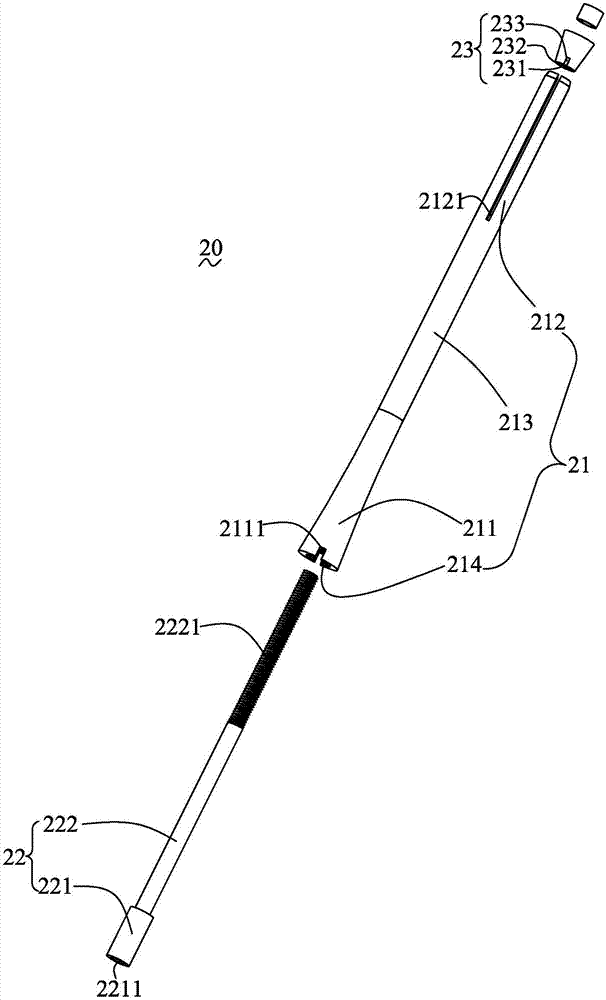
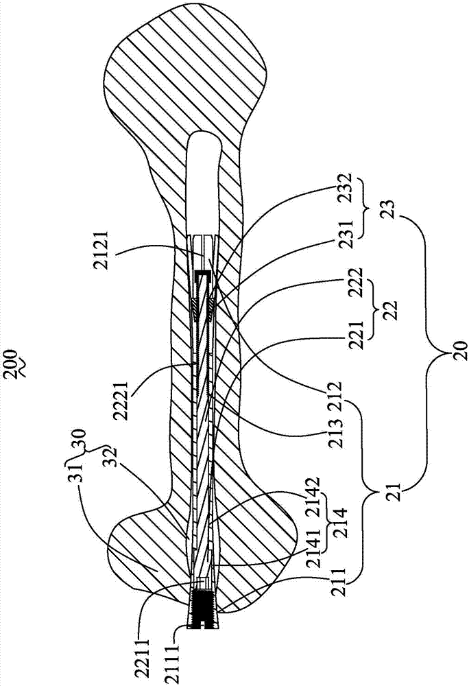
[0020] see figure 1 and figure 2 , which is a structural schematic diagram of a tibial group 100 using a tibial / humeral intramedullary nail provided by the present invention. The tibial / humeral intramedullary nail 100 includes a tibia 10 and a tibial / humeral intramedullary nail 20 inserted in the tibial 10 .

[0021] The tibia 10 is one of the two bones of the human lower leg, which is located on the inner side of the lower leg, plays an important role in supporting body weight, and is the main load-bearing bone in the lower leg bone. The tibia 10 can be divided into one body and two ends. The upper end expands to form the medial and lateral condyles, which form the knee joint w...


PUM


Abstract

The invention discloses a tibial/humeral intramedullary nail and a tibial group and a humeral group using the tibial/humeral intramedullary nail. The tibial/humeral intramedullary nail comprises a main nail, a core nail and a cock. The main nail comprises a main nail tail and a hollowed cavity. The hollowed cavity comprises a large-diameter cavity which is arranged in a main nail head. The main nail tail comprises at least one split groove. A core nail head is accommodated within the large-diameter cavity and the core nail head is greater than a small-diameter cavity in diameter. An outer screw thread is arranged at the tail of a core nail body. The cock comprises an inner screw thread. The contour line of a cross section of the cock, along an axial direction of the main nail, is represented as an isosceles triangle. The inner and outer screw threads are coupled, so that the cock is arranged at the tail of the core nail body. The tibial/humeral intramedullary nail, which is provided with the core nail and the cock, has a self-locking function, so that a fixed screw is prevented, and subsequently, operations are simplified and facilitated and using cost is reduced.

Description


Claims


Application Information

Patent Timeline
Owner JIAOZUO XINGANG MEDICAL EQUIP
Why Eureka
Try Eureka