Pushing device for scalper sieve tray

A technology of pushing device and sifting machine, which is applied in the direction of sieve, solid separation, grille, etc., can solve the problems of broken push rod, push rod bending, etc., and achieve the effect of safe and stable operation.

Inactive Publication Date: 2017-10-20
蔡敬东
View PDF4 Cites 0 Cited by
  • Summary
  • Abstract
  • Description
  • Claims
  • Application Information

AI Technical Summary

Problems solved by technology

And the existing pushing device that is used for the sieve tray of the grain sieving machine still has some deficiencies in use, and the sieve tray is directly connected with the push rod of the pushing device, which often leads to excessive loading of the sieve tray. Breaking the push rod when it is too large, or causing the push rod to bend

Method used


Image

  • Pushing device for scalper sieve tray
  • Pushing device for scalper sieve tray
  • Pushing device for scalper sieve tray

Examples


Embodiment Construction

[0020] The preferred embodiments of the present invention will be described in detail below in conjunction with the accompanying drawings, so that the advantages and features of the present invention can be more easily understood by those skilled in the art, so as to define the protection scope of the present invention more clearly.

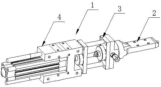
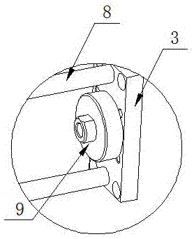
[0021] Such as Figure 1 to Figure 6 As shown, the pushing device 1 for the sieve tray of the grain sieving machine includes a fixed frame 4, and a motor 5 is installed inside the fixed frame 4, and a movable disc 6 is installed on one side of the fixed frame 4, and a movable plate 6 is installed inside the motor 5. Push rod 7, the push rod 7 runs through the movable disc 6, a push disc 3 is installed on one side of the movable disc 6, a disc 9 is welded in the middle of the side wall of the push disc 3, and one end of the push rod 7 is inserted through the disc 9 Inside, a sliding rod 8 is welded on both sides of the disc 9, the sliding rod 8 ru...


PUM


Abstract

The invention discloses a pushing device for a scalper sieve tray. The pushing device comprises a fixing frame. A motor is mounted in the fixing frame. A movable plate is mounted on one side of the fixing frame. A pushing rod is mounted in the motor and penetrates through the movable plate. A disc is welded to the middle of the side wall of a pushing plate. The tail end of an inner rod is inserted into a threaded hole in a penetrating mode. A nut is arranged at the tail end of the inner rod in a sleeving mode. By mounting the movable plate between the fixing frame and the pushing plate and mounting two sliding rods between the pushing plate and the movable plate, the pushing plate is driven to move back and forth through telescoping of the pushing rod, thus, the effect that the sieve tray mounted on a connecting base is driven to sieve grains back and forth is achieved, due to the fact that the pushing rod is welded between the two sliding rods, the pushing rod is not directly connected to the connecting base, the sliding rods can share loads of the pushing rod, and the situation that the pushing rod is bent or even broken due to too heavy grains on the sieve tray is effectively avoided.

Description

technical field [0001] The invention relates to a pushing device, more precisely, a pushing device for a sieve tray of a grain sieving machine. Background technique [0002] Grain sieving machine is a device used to sieve grains. Its operating principle is: use the push device to push the grains to be sieved on the sieve plate back and forth to form a reciprocating motion, so as to realize the sieving of grains. And the existing pushing device that is used for the sieve tray of the grain sieving machine still has some deficiencies in use, and the sieve tray is directly connected with the push rod of the pushing device, which often leads to excessive loading of the sieve tray. Break the push rod when it is too large, or cause the push rod to bend. Contents of the invention [0003] The invention mainly solves the technical problems existing in the prior art, thereby providing a pushing device for the sieve tray of a grain sieving machine. [0004] Above-mentioned technica...

Claims


Application Information

Patent Timeline
IPC IPC(8): B07B1/42B07B1/28
CPCB07B1/42B07B1/28
Inventor 蔡敬东
Owner 蔡敬东
Why Eureka
Try Eureka