An indoor led ceiling lamp device

A technology for LED ceiling lamps and lamp holders, which is applied to lighting devices, fixed lighting devices, lighting device components, etc. It can solve the problems of inconvenient quick installation of LED ceiling lamps, cumbersome installation operations, and roof damage, etc., and achieve overall operation safety Reliable, simple and convenient installation and disassembly operation, and the effect of increasing stability

Active Publication Date: 2018-05-08
浙江宙辉电器有限公司
View PDF5 Cites 4 Cited by
  • Summary
  • Abstract
  • Description
  • Claims
  • Application Information

AI Technical Summary

Problems solved by technology

[0002] LED ceiling light is a kind of LED ceiling light, which is installed inside the room. Its appearance is designed to be relatively flat on the upper part. High efficiency, low power consumption, long life, easy control, energy saving and environmental protection are widely used, but the existing LED ceiling lamps need to pre-embed bolts on the roof or fix them on the roof with expansion bolts during installation. The installation method will not only cause damage to the roof, but also the installation operation is relatively cumbersome, which is not convenient for the rapid installation of LED ceiling lamps, and the existing LED ceiling lamps are installed after first connecting the wires to the LED ceiling lamps and then fixing them. It is easy to cause electric shock accidents

Method used


Image

  • An indoor led ceiling lamp device
  • An indoor led ceiling lamp device
  • An indoor led ceiling lamp device

Examples


Embodiment Construction

[0018] The preferred embodiments of the present invention will be described in detail below in conjunction with the accompanying drawings, so that the advantages and features of the present invention can be more easily understood by those skilled in the art, so as to define the protection scope of the present invention more clearly.

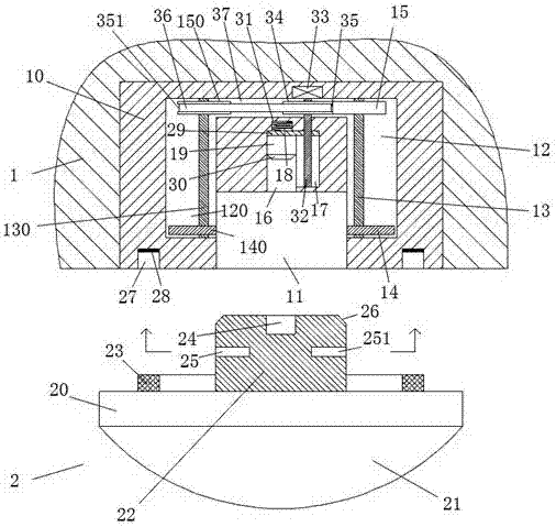
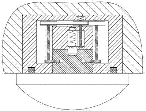
[0019] refer to Figure 1-4 The shown indoor LED ceiling lamp device includes a lamp holder body 10 installed in the roof 1 and a lamp holder body 2 mated with the lamp holder body 10, and the lower end surface of the lamp holder body 10 is provided with a downward opening in the middle. Inserting chamber 11, the left and right moving chambers 120 and 12 extending upward are arranged symmetrically at the left and right ends of the inserting chamber 11 in the lamp holder body 10 respectively, and the left and right moving chambers 120 and 12 There is a driving cavity 37 communicated between the upper parts, and the left locking part and the right ...


PUM


Abstract

The invention discloses an indoor LED ceiling lamp device. The indoor LED ceiling lamp device comprises a lamp holder body mounted in a ceiling and a lamp head body which is connected with the lamp holder body in a matched mode, wherein an insertion cavity with a downward opening is formed in the middle of the lower end surface of the lamp holder body; positions, at the left end and the right end of the insertion cavity, in the lamp holder body are symmetrically equipped with a left motion cavity and a right motion cavity which extend upwards separately; a drive cavity is arranged between the upper part of the left motion cavity and the upper part of the right motion cavity in a communication mode; and a left locking part and a right locking part are separately arranged in the left motion cavity and the right motion cavity. The indoor LED ceiling lamp device is simple in integral structure, is safe and reliable in integral operation, is high in efficiency of mounting and dismounting an LED ceiling lamp, and effectively avoids electric shock accident when the LED ceiling lamp is mounted and dismounted, and therefore, life safety of mounting staff is guaranteed, and the whole device is simple and convenient in mounting and dismounting operation, and is suitable for being popularized and used.

Description

technical field [0001] The invention relates to the technical field of LED lamps, in particular to an indoor LED ceiling lamp device. Background technique [0002] LED ceiling light is a kind of LED ceiling light, which is installed inside the room. Its appearance is designed to be relatively flat on the upper part. High efficiency, low power consumption, long life, easy control, energy saving and environmental protection are widely used, but the existing LED ceiling lamps need to pre-embed bolts on the roof or fix them on the roof with expansion bolts during installation. The installation method will not only cause damage to the roof, but also the installation operation is relatively cumbersome, which is not convenient for the rapid installation of LED ceiling lamps, and the existing LED ceiling lamps are installed after first connecting the wires to the LED ceiling lamps and then fixing them. It is easy to cause electric shock accidents. Contents of the invention [00...

Claims


Application Information

Patent Timeline
Patent Type & Authority Patents(China)
IPC IPC(8): F21S8/00F21V17/16F21V17/18F21V25/00F21Y115/10
CPCF21S8/00F21V17/164F21V17/18F21V25/00F21Y2115/10
Inventor 陈玄德
Owner 浙江宙辉电器有限公司
Why Eureka
Try Eureka