Mixing machine for building construction

A technology of building construction and mixer, applied in the direction of unloading device, cement mixing device, control device, etc., can solve the problems of cumbersome and laborious operation process, affect the construction progress, and high cost of use, so as to reduce operation steps and reduce work The effect of low quantity and production cost

Inactive Publication Date: 2017-10-24
晋江市东坤电子实业有限公司
View PDF7 Cites 3 Cited by
  • Summary
  • Abstract
  • Description
  • Claims
  • Application Information

AI Technical Summary

Problems solved by technology

[0002] Concrete is the most used building material. Now almost all engineering buildings use concrete. It is mainly made of cement, sand, stone and water after mixing. In traditional technology, the mixing of concrete is done manually. The operation The process is cumbersome, laborious and inefficient. There are many concrete mixers in the prior art, but their use costs are high and they need to be operated by professionals, which seriously affects the construction progress and cannot meet the existing needs. There are major disadvantages. Need Improve

Method used


Image

  • Mixing machine for building construction
  • Mixing machine for building construction
  • Mixing machine for building construction

Examples


Embodiment Construction

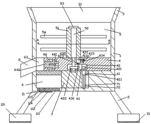
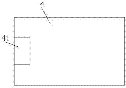
[0029] like Figure 1-Figure 9 As shown, a mixer for building construction of the present invention includes a material barrel 1, a funnel 3 with a first cavity 31 is provided on the top of the material barrel 1, and a second cavity is provided in the material barrel 1 5. The bottom wall on the left side of the second cavity 5 is provided with a third cavity 6 communicating with the second cavity 5 on the top, and the right side of the third cavity 6 is provided with an upward extension The set bearing block 7, the outer wall of the right side of the bearing block 7 is provided with a first sliding groove 71, and the first sliding groove 71 is provided with a first screw rod 72 extending up and down. The bottom of the second cavity 5 is provided with a fixed plate 4, the left side of the fixed plate 4 is provided with an opening groove 41, the inner middle end of the fixed plate 4 is provided with a drive cavity 42, and the inner top wall of the drive cavity 42 is provided wit...


PUM


Abstract

The invention discloses a mixing machine for building construction. The mixing machine comprises a material barrel, a hopper with a first containing cavity is arranged at the top of the material barrel, a second containing cavity is formed in the material barrel, a third containing cavity with the top communicated with the second containing cavity is arranged in the bottom wall of the left side of the second containing cavity, and a bearing block extending upwards is arranged on the right side of the interior of the third containing cavity; a first slippage groove is formed in the outer wall of the right side of the bearing block, a first spiral rod extending up and down is arranged in the first slippage groove, a fixing plate is arranged at the bottom of the interior of the second containing cavity, an opening groove is formed in the left side of the fixing plate, and a driving cavity is formed in the middle end of the interior of the fixing plate; a second slippage groove is formed in the top wall of the interior of the driving cavity, a guide movement rod is arranged in the second slippage groove, a first slippage cavity is connected to the guide movement rod in a slippage manner, and a rotary pin shaft extending upwards is arranged in the driving cavity and penetrates the top wall of the fixing plate to penetrate the second containing cavity; and the rotary pin shaft tail in the second containing cavity is fixedly provided with an upwards-extending outer spline shaft.

Description

technical field [0001] The invention relates to the technical field of building construction, in particular to a mixer for building construction. Background technique [0002] Concrete is the most used building material. Now almost all engineering buildings use concrete. It is mainly made of cement, sand, stone and water after mixing. In traditional technology, the mixing of concrete is done manually. The operation The process is cumbersome, laborious and inefficient. There are many concrete mixers in the prior art, but their use costs are high and they need to be operated by professionals, which seriously affects the construction progress and cannot meet the existing needs. There are major disadvantages. Need Improve. Contents of the invention [0003] The technical problem to be solved by the present invention is to provide a mixer for building construction, which can solve the above-mentioned problems in the prior art. [0004] The present invention is achieved throug...

Claims


Application Information

Patent Timeline
Patent Type & Authority Applications(China)
IPC IPC(8): B28C5/16B28C7/16B28C7/02
CPCB28C5/16B28C5/0806B28C5/0831B28C7/02B28C7/16
Inventor 俞海东
Owner 晋江市东坤电子实业有限公司
Why Eureka
Try Eureka