Ship stern shaft sealing device

A technology of sealing device and stern shaft, which is applied in the direction of engine sealing, engine components, mechanical equipment, etc., and can solve the problem that the sealing ring does not have a good sealing effect on the sealing end cover.

Active Publication Date: 2017-10-24
江苏德立密封科技有限公司
View PDF6 Cites 11 Cited by
  • Summary
  • Abstract
  • Description
  • Claims
  • Application Information

AI Technical Summary

Problems solved by technology

[0002] At present, the marine stern shaft sealing device generally includes a stern shaft, a sealing end cover, and a sealing ring; the sealing ring is fastened on the stern shaft, and the sealing ring abuts against the inner surface of the sealing end cover through an elastic pressure-resisting mechanism, so The stern shaft and the sealing end cover are sealed by the sealing ring, but during the long-term use of the stern shaft, the stern shaft will be displaced in the axial direction, and the stern shaft will drive the sealing ring to move, so that the degree of pressure resistance of the sealing ring and the sealing end cover Changes occur, causing the sealing ring to not have a good sealing effect on the sealing end cap

Method used


Image

  • Ship stern shaft sealing device
  • Ship stern shaft sealing device

Examples


Embodiment Construction

[0013] The content of the present invention will be further described in detail below in conjunction with the accompanying drawings.

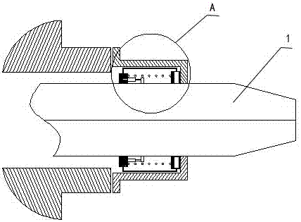
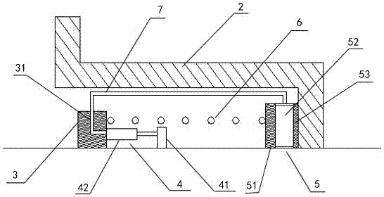
[0014] Such as figure 1 and 2 As shown, a marine stern shaft sealing device includes a stern shaft 1 , a sealing end cover 2 , an annular positioning plate 3 , an inflation device 4 , and a sealing ring body 5 . The sealing end cover 2 is fixed on the outside of the stern shaft 1 . The annular positioning plate 3 is installed on the outside of the stern shaft 1 . The sealing ring body 5 abuts against the joint of the sealing end cover 2 and the stern shaft 1 . An elastic body 6 is installed between the annular positioning plate 3 and the sealing ring body 5 . The inflation device 4 includes a piston 41 and an air cylinder 42 . One end of the piston 41 extends into the cylinder 42, and the bottom of the piston 41 is fixed on the stern shaft 1. The sealing ring body 5 includes a pressure plate 51 , an air bag 52 and a sealing sheet 53 . Th...


PUM


Abstract

The invention discloses a ship stern shaft sealing device. The ship stern shaft sealing device comprises a stern shaft, a sealing end cover, an annular positioning plate, an air inflation device and a sealing ring body. The sealing end cover is fixed to the outer side of the stern shaft. The annular positioning plate is installed on the outer side of the stern shaft. The sealing ring body abuts against the joint between the sealing end cover and the stern shaft. An elastomer is installed between the annular positioning plate and the sealing ring body. The air inflation device comprises a piston and an inflator. One end of the piston extends into the inflator, and the bottom of the piston is fixed to the stern shaft. The sealing ring body comprises an abutting pressure plate, an air bag and a sealing slice. The two sides of the air bag are fixed to the abutting pressure plate and the sealing slice correspondingly. The bottom of the abutting pressure plate and the bottom of the sealing slice are fixed to the stern shaft. One side of the sealing slice abuts against the inner side of the sealing end cover. The inflator communicates with the outer side of the air bag through an air pipe. According to the ship stern shaft sealing device, axial displacement compensation is achieved through expansion of the air bag, and the sealing performance of the device is not influenced.

Description

technical field [0001] The invention relates to a marine stern shaft sealing device. Background technique [0002] At present, the marine stern shaft sealing device generally includes a stern shaft, a sealing end cover, and a sealing ring; the sealing ring is fastened on the stern shaft, and the sealing ring abuts against the inner surface of the sealing end cover through an elastic pressure-resisting mechanism, so The stern shaft and the sealing end cover are sealed by the sealing ring, but during the long-term use of the stern shaft, the stern shaft will be displaced in the axial direction, and the stern shaft will drive the sealing ring to move, so that the degree of pressure resistance of the sealing ring and the sealing end cover Changes occur, causing the sealing ring to not have a good sealing effect on the sealing end cap. Contents of the invention [0003] Aiming at the shortcomings of the above-mentioned prior art, the problem to be solved by the present inventi...

Claims


Application Information

Patent Timeline
Patent Type & Authority Applications(China)
IPC IPC(8): F16J15/46F16J15/16
CPCF16J15/164F16J15/46
Inventor 汪子昂陶伟陆晖绣
Owner 江苏德立密封科技有限公司
Why Eureka
Try Eureka