Three-electrode solid electrolyte electrochemical reactor

A solid electrolyte and solid electrolyte membrane technology, applied in the field of electrochemistry, can solve the problems of affecting the sealing performance and internal resistance of the reactor, and easy to influence each other, and achieve the effect of convenient use and maintenance, and stable monitoring.

Active Publication Date: 2016-07-20
碳能环保技术(潍坊)有限公司
View PDF6 Cites 9 Cited by
  • Summary
  • Abstract
  • Description
  • Claims
  • Application Information

AI Technical Summary

Problems solved by technology

These schemes can monitor the potential of the working electrode in real time, but the potential of the working electrode and the reference electrode are likely to a

Method used


Image

  • Three-electrode solid electrolyte electrochemical reactor
  • Three-electrode solid electrolyte electrochemical reactor
  • Three-electrode solid electrolyte electrochemical reactor

Examples


Embodiment 1

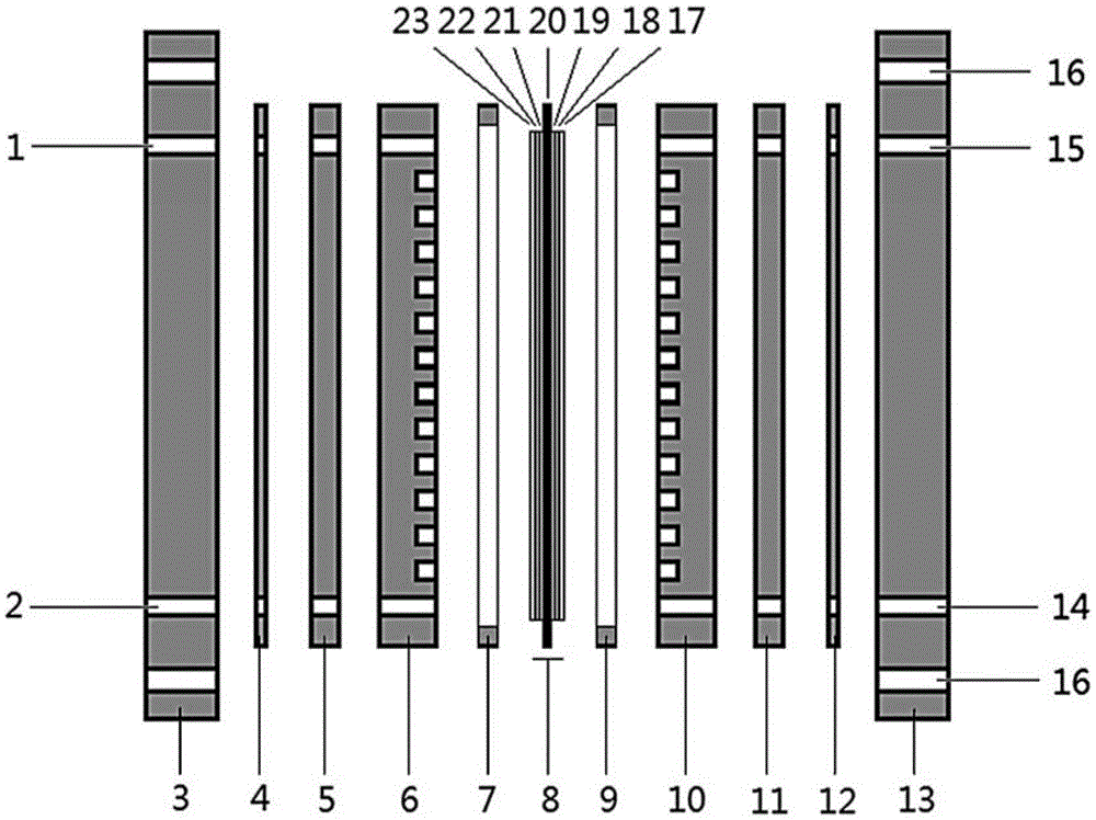
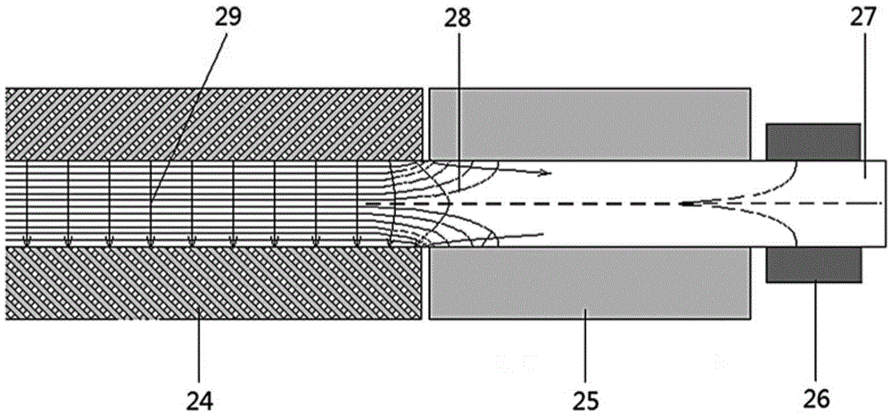
[0070] Such as figure 1 As shown, the monolithic solid electrolyte electrochemical reactor consists of basic structure and auxiliary structure. The basic structure includes cathode flow field plate 6 , membrane electrode assembly 8 and anode flow field plate 10 . In addition to the corresponding catalyst layers 21,19, the cathode surface and the anode surface on the membrane electrode assembly 8 can also have microporous layers 22,18, support layers 23,17, etc.; the catalyst layer 21 on the cathode surface of the membrane electrode assembly 8 , microporous layer 22, support layer 23, etc. and the cathode flow field plate 6 constitute the cathode, and the catalyst layer 19, microporous layer 18, support layer 17, etc. on the other side and the anode flow field plate 10 constitute the anode. Both the cathode and anode flow field plates 6 and 10 are made of inert electronically conductive material, and one side thereof has flow grooves to distribute the reactant fluid to the ent...

Embodiment 2

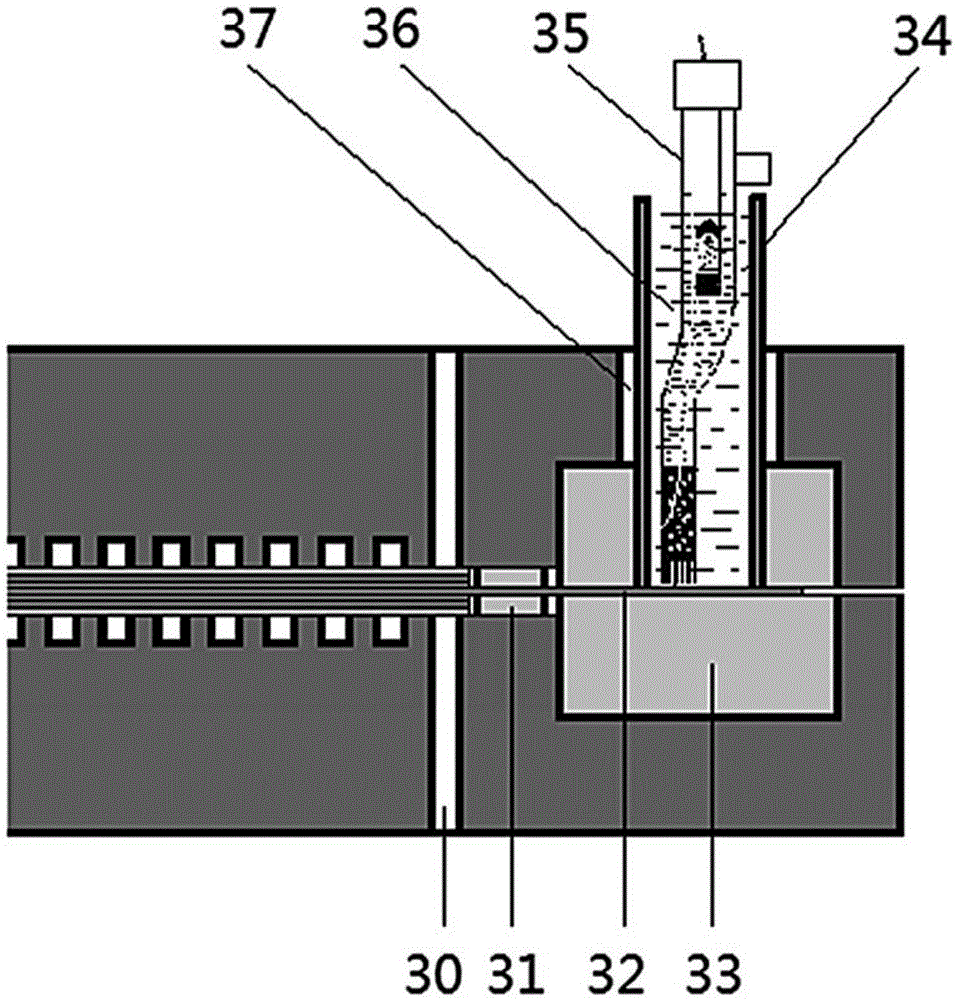
[0076] Such as Figure 8 As shown, when the flow field plate is not thick enough, for example, less than 4mm, the reference electrode sealing gasket 33 can be placed by using part of the thickness of the current collector plate 5 or even the splint 3 . Other structures are with embodiment 1. In order to show the connection of the reference electrode 35 more clearly, a part of the reactor is omitted in the figure, the same below.

Embodiment 3

[0078] Sometimes in order to reduce the expansion of the electrochemical reactor, it may be necessary to use a thinner reference electrode tube 34 or a reference electrode installation hole 37 , so that the reference electrode 35 cannot be directly inserted into the reference electrode tube 34 . In this case, the ionic connection of the electrolyte membrane to the reference electrode 35 can be achieved by means of a salt bridge 39, such as Figure 9 shown. Other structures are with embodiment 2 or embodiment 3.


PUM


Abstract

The invention provides a three-electrode solid electrolyte electrochemical reactor, which comprises a membrane electrode assembly, a flow field plate, a sealing gasket and a reference electrode, wherein the membrane electrode assembly comprises an active area and an inactive area capable of generating electrochemical reaction; the inactive area is located on the periphery of the active area; the inactive area is an exposed area of a solid electrolyte membrane; the flow field plate comprises a cathode flow field plate and an anode flow field plate; the membrane electrode assembly is clamped between the cathode flow field plate and the anode flow field plate; the sealing gasket is arranged between the membrane electrode assembly and the flow field plate and is located in the inactive area of the membrane electrode assembly; an access point of the reference electrode is arranged outside the sealing gasket; and ion connection is kept with the inactive area through an electrolyte solution or under an assist of the solid electrolyte membrane. The electrochemical reactor provided by the invention can start or cancel monitoring by the reference electrode at any time, does not affect the working states of an anode and a cathode and does not affect the structure and the air-tightness of the reactor.

Description

technical field [0001] The invention relates to the field of electrochemistry, in particular to a three-electrode solid electrolyte electrochemical reactor. Background technique [0002] Solid electrolyte electrochemical reactors (including batteries and electrolytic cells) are compact energy conversion devices. Its core functional unit includes three parts: cathode, anode and solid electrolyte membrane, and cathode and anode catalysts and membranes are generally used in a three-in-one form (ie, membrane electrode assembly 8 complex). In order to evaluate and optimize the respective contributions of the cathode and anode, in order to prevent the cathode and anode from overloading, corrosion or other damage, during the operation of the reactor, in addition to monitoring the potential difference between the cathode and anode (reactor voltage), real-time and accurate The respective potentials of the cathode and anode are monitored. This requires the introduction of a referenc...

Claims


Application Information

Patent Timeline
IPC IPC(8): H01M8/04537H01M8/1011H01M8/10C25B9/00
CPCC25B9/00H01M8/04544H01M8/1011Y02E60/50
Inventor 张红飞康鹏
Owner 碳能环保技术(潍坊)有限公司
Why Eureka
Try Eureka