Brake control valve of airplane

A brake control valve and aircraft technology, which is applied to the aircraft brake arrangement, control mechanism, hydraulic brake transmission device and other directions, can solve problems such as the inability to meet the requirements of aircraft brake anti-skid control, achieve good working stability and reliability, improve Work stability and reliability, easy to use and maintain

Inactive Publication Date: 2013-06-12
XIAN AVIATION BRAKE TECH
View PDF7 Cites 21 Cited by
  • Summary
  • Abstract
  • Description
  • Claims
  • Application Information

AI Technical Summary

Problems solved by technology

[0005] In order to overcome the deficiencies in the prior art that cannot meet the requirements of aircraft brake anti-skid control, the present invention proposes an aircraft brake control valve

Method used


Image

  • Brake control valve of airplane
  • Brake control valve of airplane

Examples


Embodiment 1

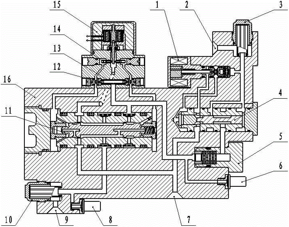
[0024] Such as figure 1 shown. This embodiment is an aircraft brake control valve, including: an electromagnetic hydraulic lock and an electro-hydraulic pressure servo valve. The electromagnetic hydraulic lock includes a solenoid valve 1, an aircraft brake control valve oil inlet 2, an inlet oil filter 3, a switching valve 4, a throttle 5 and a pressure sensor 6. The electro-hydraulic pressure servo valve consists of a slide valve 11, a brake port oil filter 10, a brake port pressure sensor 8, an orifice 12, a torque motor oil filter 13, a nozzle 14, a torque motor 15 and the like. The electromagnetic hydraulic lock and the electrohydraulic pressure servo valve are integrated on the housing 16 . The torque motor 15 adopts the prior art and is fixed on one side of the housing 16 . The two ends of the nozzle of the torque motor 15 communicate with the upper outlets of the throttle holes 12 at both ends of the torque motor oil filter through oil passages respectively. The low...

Embodiment 2

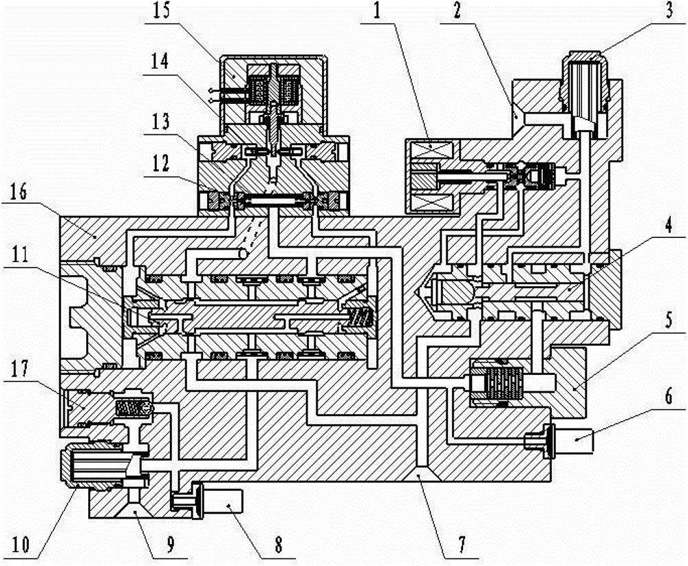
[0030] Such as figure 2shown. This embodiment is an aircraft brake control valve, including: an electromagnetic hydraulic lock and an electro-hydraulic pressure servo valve. The electromagnetic hydraulic lock includes a solenoid valve 1, an aircraft brake control valve oil inlet 2, an inlet oil filter 3, a switching valve 4, a throttle 5 and a pressure sensor 6. The electro-hydraulic pressure servo valve includes a slide valve 11, a brake port oil filter 10, a brake port pressure sensor 8, an orifice 12, a torque motor oil filter 13, a nozzle 14, a one-way valve 17 and a torque motor 15. The electromagnetic hydraulic lock and the electrohydraulic pressure servo valve are integrated on the housing 16 . The torque motor 15 adopts the prior art and is fixed on one side of the housing 16 . The two ends of the nozzle of the torque motor 15 communicate with the upper outlets of the throttle holes 12 at both ends of the torque motor oil filter through oil passages respectively. ...


PUM


Abstract

A brake control valve of an airplane is characterized in that two ends of a jet nozzle of a torque motor are communicated with those of a slide valve control cavity through an outlet of an orifice; the brake port of the brake control valve of the airplane is communicated with that of the slide valve through an oil line; a brake port oil filter is serially connected between the brake port of the slide valve and that of the brake control valve of the airplane; the oil inlet of a brake port pressure sensor is connected to the oil line between the brake port of the slide valve and the oil inlet of the brake port oil filter; the oil inlet is communicated with that of a change-over valve through the oil line; a solenoid valve is serially connected to the oil line between the oil inlet and that of the change-over valve; an inlet filter is serially connected between the solenoid valve and the oil inlet; the oil inlet of a flow controller is communicated with the oil outlet of the change-over valve through the oil line; and the oil inlet of the pressure sensor is communicated with the oil line at the outlet of the flow controller through a pipeline. The brake control valve has good working stability and reliability, and provides inlet pressure and outlet pressure signals.

Description

technical field [0001] The technical invention relates to an electro-hydraulic pressure servo valve. Specifically, the invention relates to an improved modularized electro-hydraulic pressure servo brake control valve used in an aircraft fly-by-wire brake system. Background technique [0002] The basic composition of the modern aircraft fly-by-wire braking system includes a brake command sensor, a wheel speed sensor, an electronic anti-skid brake control box and a brake control valve. In order to meet the control accuracy requirements, electro-hydraulic pressure servo valves are usually used as brake / anti-skid control valves to precisely control the brake pressure of the wheels, prevent tires from bursting, and shorten the braking distance. At the same time, since the brake command sensor replaces the brake valve, in order to reduce unnecessary energy consumption of the hydraulic pressure supply system under non-braking conditions, an electromagnetic hydraulic lock (electrom...

Claims


Application Information

Patent Timeline
Patent Type & Authority Applications(China)
IPC IPC(8): B60T11/28B64C25/44
Inventor 何永乐马建峰
Owner XIAN AVIATION BRAKE TECH
Why Eureka
Try Eureka