Pressure independent pressure-producing system

A pressure and pre-pressing pump technology, applied in the field of pressure and pressure, can solve the problems of high work intensity, damage to pressurization or overweight devices, and heavy manual labor.

Active Publication Date: 2019-09-27
大连普瑞森科技有限公司
View PDF12 Cites 0 Cited by
  • Summary
  • Abstract
  • Description
  • Claims
  • Application Information

AI Technical Summary

Problems solved by technology

At present, the pressure generation and control of piston pressure gauges are all realized by manually providing power. The possible problem is that when a large pressure needs to be loaded, the operator needs to provide a lot of force to achieve it, resulting in artificial manual labor. Larger, especially the operators of the pressure gauge detection are mostly women, and the work intensity is high and the efficiency is low to achieve high pressure pressure; at the same time, due to the manual operation to achieve pressure pressure, it is easily affected by factors such as the operator's emotion and experience , when used in conjunction with a system such as a weighting device, a certain specific pressure formed is completely achieved by manual control, resulting in a large or small pressure loading, an unstable process, or even damage to the pressure or weighting device; during the loading process, it is necessary Manually operate the switch valve, the operator's strength is unstable, and it is easy to cause pressure leakage

Method used


Image

  • Pressure independent pressure-producing system
  • Pressure independent pressure-producing system
  • Pressure independent pressure-producing system

Examples


Embodiment Construction

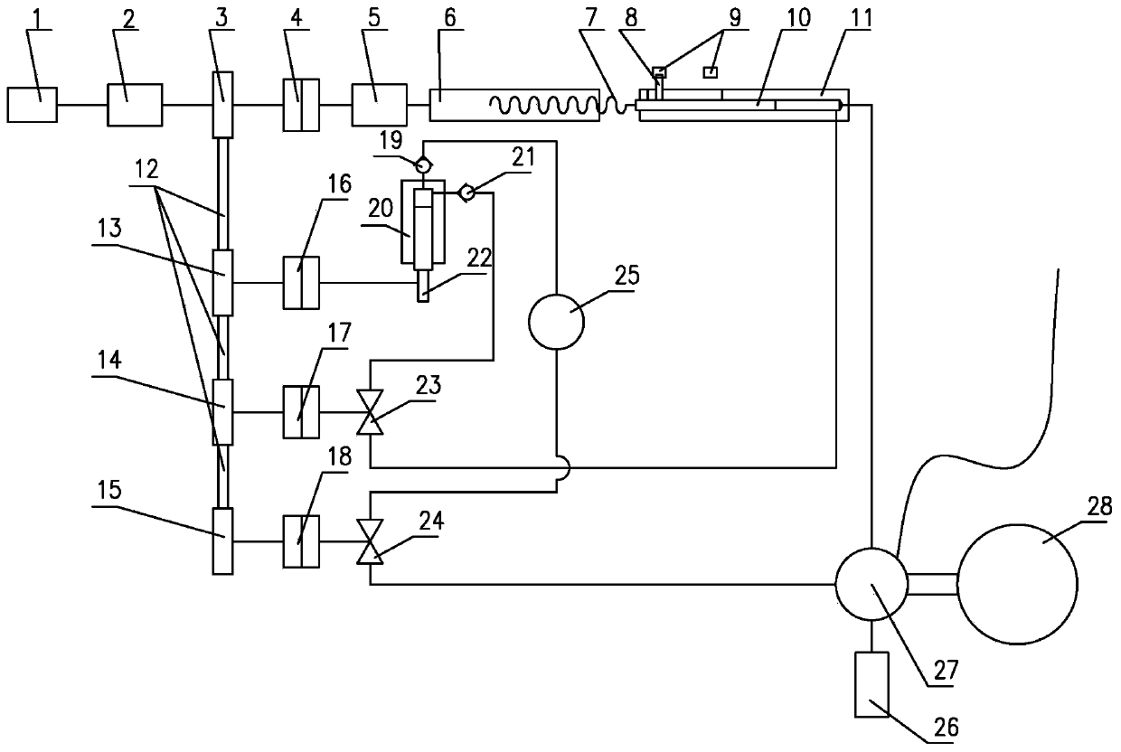
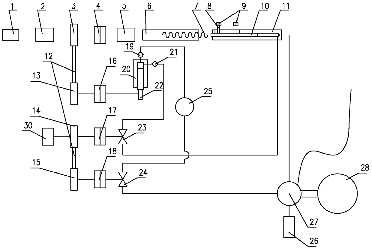
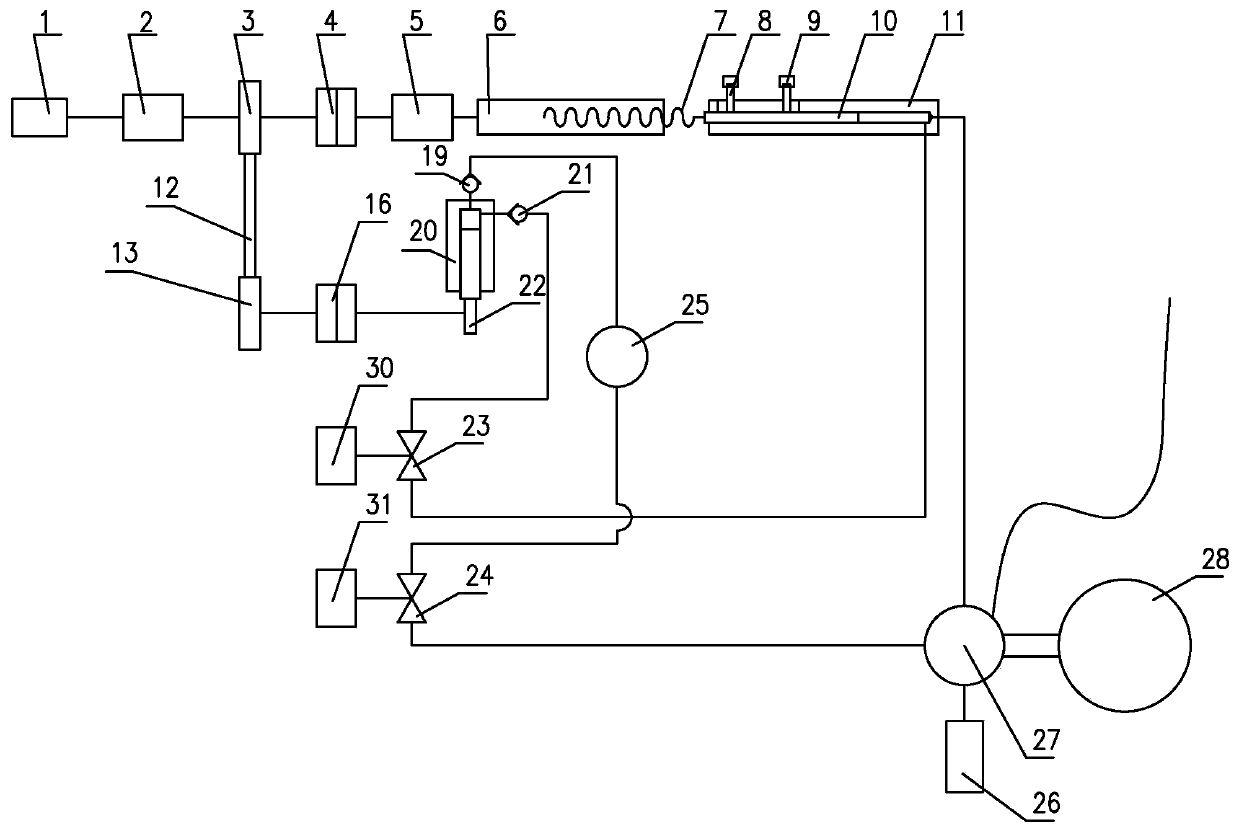
[0019] Such as figure 1 As shown, a pressure generating system controlled by a servo motor: the first servo motor 1 is connected to the first reducer 2, the speed of the first servo motor 1 is reduced to increase the torque, the first reducer 2 is connected to the transmission shaft, and the transmission The first sprocket 3 and the first clutch 4 are installed on the shaft to realize the transmission of speed and torque. The first clutch 4 is connected with the second reducer 5 to reduce the speed of the first servo motor 1 and increase the torque. The second speed reducer 5 is connected with the screw sleeve 6, the screw sleeve 6 is matched with the screw rod 7, and the screw rod 7 is connected with the piston 10. The rotation of the first servo motor drives the piston 10 to move linearly in the piston cylinder 11 to compress the hydraulic oil in the piston cylinder 11 to increase the pressure. The piston 10 is installed with a screw 8, the screw 8 is installed with a light s...


PUM


Abstract

The invention discloses a pressure-producing system. The pressure-producing system comprises a piston cylinder (11) and a piston (10) for producing pressure, wherein the piston (10) is connected with a screw rod (7), and the screw rod is connected with an axially fixed screw rod sleeve (6); the screw rod sleeve is connected with a first servo motor (1) for driving the screw rod sleeve to rotate through a clutch (4); the pressure output end of the piston cylinder is connected with a meter connecting seat (27) of a pressure meter (28) and a pressure release valve (24) in parallel; the pressure cavity at the rear part of the pressure output end of the piston cylinder is connected with the output end of a pressure increasing valve (23), and the oil supply end of the pressure increasing valve is connected with the oil outlet of a precompression pump (20); an oil inlet of the precompression pump is connected with an oil cup (25); and the pumping actuating mechanism of the precompression pump, the opening and closing actuating mechanism of the pressure release valve and the opening and closing actuating mechanism of the pressure increasing valve are connected with a power output part through the clutch. The pressure-producing system has the characteristics of simplicity in operation, convenience in use and high efficiency, can be used in combination with a weight loading system, achieves an automatic piston pressure measuring robot, and solves the problems of the existing piston pressure gauge.

Description

Technical field [0001] The present invention relates to a pressure generating technology during pressure gauge measurement, and more particularly to a pressure generating device suitable for a piston type pressure measuring robot. Background technique [0002] Pressure is one of the important process parameters in industrial production, and the pressure gauge is an instrument used to measure pressure. If the pressure does not meet the requirements, it will not only affect production efficiency, reduce product quality, and even cause serious safety accidents, so pressure measurement has a special position in industrial production. Therefore, the pressure gauge must be calibrated when it leaves the factory or after a certain period of use. The instrument used is a piston pressure gauge. The piston pressure gauge integrates pressure generation and pressure calibration, and is equipped with appropriate precision weights, which can verify and measure the measured object with correspo...

Claims


Application Information

Patent Timeline
Patent Type & Authority Applications(China)
IPC IPC(8): G01L27/00F16K31/04F15B19/00
CPCF15B19/00F16K31/043G01L27/005
Inventor 庞桂兵卜繁岭高腾吴洪威
Owner 大连普瑞森科技有限公司
Why Eureka
Try Eureka