Electric working machine

A working machine, electric technology, applied in the direction of motor control, motor generator control, motor generator testing, etc., can solve the problems of loose front-end tools, unable to generate braking force, unable to fully exert braking function and other problems

Active Publication Date: 2017-10-31
MAKITA CORP
View PDF12 Cites 1 Cited by
  • Summary
  • Abstract
  • Description
  • Claims
  • Application Information

AI Technical Summary

Problems solved by technology

[0005] In addition, although the above-mentioned braking function can be realized by a circuit that flows a braking current into the motor to generate a braking force as described in Patent Document 1, or a braking device that directly applies a braking force to the rotating shaft of the motor, if these brakes If the moving part fails, the desired braking force cannot be produced.
[0006] In addition, for exa

Method used


Image

  • Electric working machine
  • Electric working machine
  • Electric working machine

Examples


Embodiment Construction

[0024] Embodiments of the present invention will be described below with reference to the drawings.

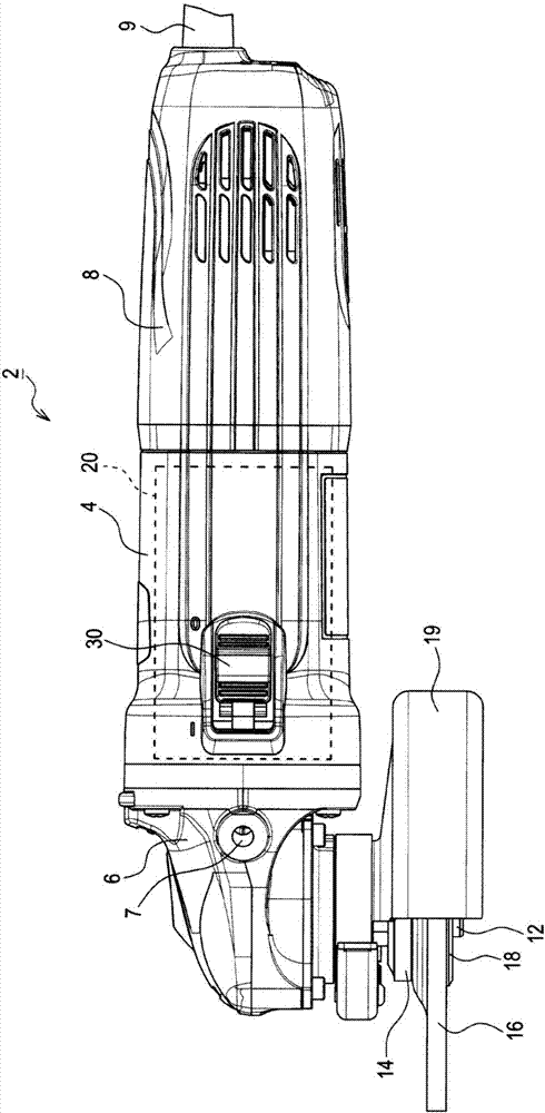
[0025] Such as figure 1 As shown, the grinder 2 of this embodiment is mainly composed of a motor housing 4 , a gear housing 6 , and a rear cover 8 .

[0026] The motor case 4 is a substantially cylindrical case and accommodates the motor 20 . The motor 20 is accommodated in the motor case 4 such that its rotation axis is parallel to the central axis of the motor case 4 , and one end of the rotation shaft protrudes toward the gear case 6 side.

[0027] Further, the rotation shaft of the motor 20 is connected to the main shaft 12 protruding outward from the gear case 6 via a gear mechanism provided in the gear case 6 .

[0028] The main shaft 12 is provided rotatably in the gear case 6 in such a manner that the central axis is perpendicular to the rotation shaft of the motor 20, and the gear mechanism in the gear case 6 is constituted by using bevel gears or the like so as to ...


PUM


Abstract

An electric working machine comprises a motor, a switch, a drive device, a brake device, and a failure determiner. The switch is configured for operation by a user, has an on-state and an off-state. The drive device is configured to drive the motor in response to the switch being placed in the on-state. The brake device is configured to control deceleration of the motor to a stopped state in response to the switch being placed in the off-state. The failure determiner is configured to monitor deceleration of the motor during controlled deceleration and to determine whether the brake device has failed based on the monitored deceleration.

Description

technical field [0001] The present invention relates to an electric working machine having a braking function for generating a braking force after driving of a motor stops. Background technique [0002] Conventionally, there is known a device having a braking function in which a braking current flows into the motor to quickly stop the motor when the drive of the motor as a power source is stopped in an electric working machine such as an electric tool (for example, refer to Patent Document 1). [0003] According to such an electric working machine, when the user turns off the operation switch to stop the driving of the motor, it is possible to prevent the tool such as the grinding wheel and the rotary cutter from continuing to rotate due to inertia, thereby improving safety. [0004] Patent Document 1: Japanese Patent No. 5777924 [0005] In addition, although the above-mentioned braking function can be realized by a circuit that flows a braking current into the motor to g...

Claims


Application Information

Patent Timeline
IPC IPC(8): H02P29/024H02P29/028G01R31/34
CPCG01R31/343B23Q11/0085H02P3/18H02P7/295H02P25/14H02P29/0241B23Q11/0092B24B23/028B25F5/00H02P3/12H02P27/04B23Q11/0089H02P3/06H02P29/024
Inventor 中本明弘
Owner MAKITA CORP
Why Eureka
Try Eureka