
Uniform mixing apparatus for building construction

A technology for building construction and equipment, which is applied to mixer accessories, mixers with rotating stirring devices, and dissolution, etc. It can solve problems such as unfavorable use, leakage at the discharge port, and expensive use, so as to improve the efficiency of discharge and discharge. The effect of speeding up the material speed and speeding up the construction progress

Inactive Publication Date: 2017-11-03
王裕迪
View PDF0 Cites 0 Cited by
  • Summary
  • Abstract
  • Description
  • Claims
  • Application Information

AI Technical Summary

Problems solved by technology

[0002] Exterior wall coatings are often used on the exterior walls of some buildings, and exterior wall coatings are mostly in powder form, which need to be mixed with water before use. In traditional technology, the stirring of the paint before use is done manually. However, in some large construction sites The construction progress is relatively tense and many people are used to construct at the same time. The efficiency of manual mixing is extremely low, and it is difficult to meet the supply needs. There are many automatic stirring devices, but it is expensive to use and the discharge port is exposed to the outside world, which makes it easy to accumulate dust, which makes the paint very easy to be polluted during discharge, which is not conducive to use, has great disadvantages, and is difficult to meet the current Have requests

Method used


Image

  • Uniform mixing apparatus for building construction
  • Uniform mixing apparatus for building construction
  • Uniform mixing apparatus for building construction

Examples


Embodiment Construction

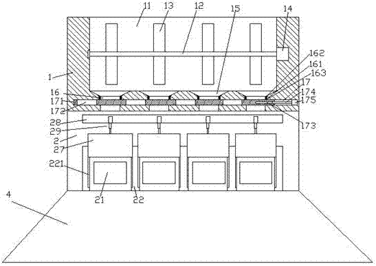
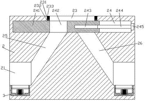
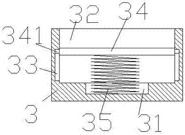
[0024] Such as Figure 1-Figure 6 As shown, a kind of stirring equipment for building construction of the present invention includes a stirring part 1 and an output part 2 arranged at the bottom of the stirring part 1 and a boss part 4 arranged at the bottom of the output part 2, so The boss part 4 is an inner hollow structure, and the inner bottom of the boss part 4 is inlaid with a counterweight, thereby increasing the support stability. The mixing part 1 is provided with a housing chamber 11, and the bottom of the housing chamber 11 is provided with There are multiple groups of bucket grooves 15, and the bottom of each bucket groove 15 is provided with a through opening 16, and the first sliding groove that penetrates through the through opening 16 and extends to the left and right sides is arranged in the through opening 16 17. The first sliding joint 17 is provided with a first sliding joint 171, the first sliding joint 171 is provided with an output hole 172, and the ins...


PUM


Abstract

The invention discloses a uniform mixing apparatus for building construction. The uniform mixing apparatus comprises a uniform mixing part, an output part arranged at the bottom of the uniform mixing part, and a boss part arranged at the bottom of the output part, wherein the boss part is of a hollow structure; the inner bottom of the boss part is inlaid with a counterweight block; an accommodation chamber is arranged in the uniform mixing part; the bottom of the accommodation chamber is provided with a plurality of hopper grooves; the bottom of each hopper groove is provided with a port; each port is internally provided with a first sliding contact groove extending leftward and rightward; each sliding contact groove is internally provided with a first sliding contact member; each first sliding contact member is internally provided with an output hole; the right side of each first sliding contact member is internally provided with a first screw-thread hole; the first screw-thread hole is internally connected with a first spiral rod in the manner of screw-thread fit; the first spiral rod is connected with a first electric motor; and the front and back outer side surfaces of the output part are both provided with a plurality of groups of acquisition zones. The uniform mixing apparatus provided by the invention is simple in structure, reasonable in design, simple and convenient to operate, capable of realizing automatic stirring and automatic discharging, improving mixing efficiency and meeting supply demands, uniform in mixing, and low in usage cost.

Description

technical field [0001] The invention relates to the technical field of building construction equipment, in particular to a mixing equipment for building construction. Background technique [0002] Exterior wall coatings are often used on the exterior walls of some buildings, and exterior wall coatings are mostly in powder form, which need to be mixed with water before use. In traditional technology, the stirring of the paint before use is done manually. However, in some large construction sites The construction progress is relatively tense and many people are used to construct at the same time. The efficiency of manual mixing is extremely low, and it is difficult to meet the supply needs. There are many automatic stirring devices, but it is expensive to use and the discharge port is exposed to the outside world, which makes it easy to accumulate dust, which makes the paint very easy to be polluted during discharge, which is not conducive to use, has great disadvantages, and ...

Claims


Application Information

Patent Timeline
Patent Type & Authority Applications(China)
IPC IPC(8): B01F7/04B01F15/02
CPCB01F27/70B01F35/7549B01F35/754551B01F2101/30
Inventor 王裕迪
Owner 王裕迪
Learn More